Tool center point calibration method and system for robot vision tool

A robot vision, tool center point technology, applied in instruments, measuring devices, optical devices, etc., can solve problems such as deviation operation and cumbersomeness, and achieve the effect of eliminating differences in technological maturity

Inactive Publication Date: 2019-06-18
精诚工科汽车系统有限公司
View PDF9 Cites 12 Cited by
  • Summary
  • Abstract
  • Description
  • Claims
  • Application Information

AI Technical Summary

Problems solved by technology

[0005] In view of this, the present invention aims to propose a tool center point calibration method for robot vision tools to at

Method used


Image

  • Tool center point calibration method and system for robot vision tool
  • Tool center point calibration method and system for robot vision tool
  • Tool center point calibration method and system for robot vision tool

Examples


Embodiment Construction

[0039] It should be noted that, in the case of no conflict, the embodiments and features in the embodiments of the present invention can be combined with each other.

[0040] The present invention will be described in detail below with reference to the drawings and in combination with embodiments.

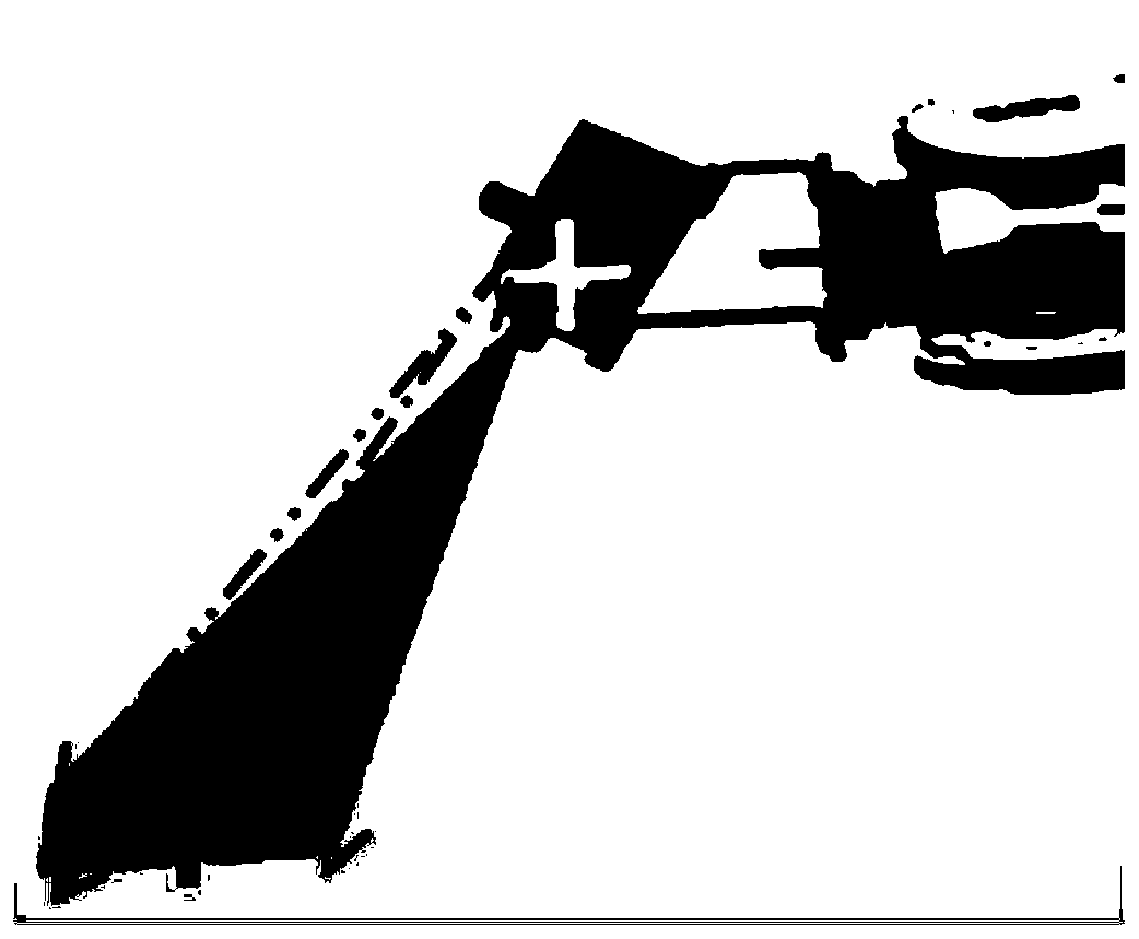
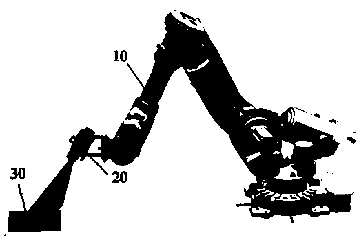
[0041] Such as image 3 As shown, an exemplary architecture of the tool center point TCP calibration method of a robot vision tool applying an embodiment of the present invention, wherein the robot (or mechanical arm) 10 is equipped with a vision system 20, and through the vision system 20, the robot can Image acquisition of the target object to manipulate the target object; and it can also be a partial reference figure 1 An example of an application where the vision system could be a robotic vision tool mounted on a flange at one end of a robotic arm. However, in order to ensure the accuracy and reliability of robot operation, it is necessary to calibrate the tool center point bef...


PUM


Abstract

The present invention belongs to the technological field of robot vision tools and provides a tool center point calibration method and system for a robot vision tool. The method includes the followingsteps that: a visual space coordinate system corresponding to a vision system is constructed according to the visual position information of a calibration reference plate collected by the vision system, wherein the calibration reference plate is capable of indicating a target object coordinate system; the calibration coordinate information of the calibration reference plate relative to a robot base coordinate system is obtained; and the tool center point of the robot vision tool is calibrated according to the calibration coordinate information and visual coordinate information corresponding to the visual position information, wherein the visual coordinate information is located in the visual space coordinate system. Therefore, multi-pose manual demonstration for a robot is not required; the automatic calibration process of the tool center point of the robot vision tool can be realized just by means of the calibration reference plate; and therefore, operation is convenient, and high precision can be realized.

Description

technical field [0001] The invention relates to the technical field of robot vision tools, in particular to a tool center point calibration method and system for robot vision tools. Background technique [0002] Such as figure 1 As shown, industrial robots complete various tasks through tools installed on the end flange, and the offset of TCP (Tool center point, tool center point) relative to the end position is mostly unknown or inaccurate , so the robot tool TCP calibration is required to calculate and identify the position of the tool end relative to the robot end coordinate system. [0003] At present, the methods used to calibrate the robot tool TCP in the related art mainly include an external measurement method and a multi-point calibration method. Among them, in the external measurement method, it is mainly completed through the auxiliary professional software of expensive high-precision measurement equipment, which is rarely used on site; in addition, in the multi...

Claims


Application Information

Patent Timeline
IPC IPC(8): G01B11/00
Inventor 赵志涛高祥李栋李建和张光辉何国川常亮刘占一周迪尹晓贺
Owner 精诚工科汽车系统有限公司
Why Eureka
Try Eureka