
Probe structure of an elastic pressure sensor

A pressure sensor and elastic technology, applied in the field of sensors, can solve the problems of inability to disassemble and replace, inconvenient installation, damage to the probe structure, etc., and achieve the effects of good heat insulation, convenient installation, and convenient fixation

Active Publication Date: 2020-06-26
苏州新意达仪器科技有限公司
View PDF6 Cites 0 Cited by
  • Summary
  • Abstract
  • Description
  • Claims
  • Application Information

AI Technical Summary

Problems solved by technology

[0004] The purpose of the present invention is to provide an elastic pressure sensor probe structure, which can solve the problem that the traditional elastic pressure sensor probe structure basically welds the diaphragm used for detection directly inside the structure, resulting in more trouble when the diaphragm is fixed. It cannot be disassembled and replaced, and the heat dissipation effect of the detection shell of the existing elastic pressure sensor probe structure is relatively general, and it is lacking in heat dissipation and heat insulation. When it is in a high temperature detection environment for a long time, it will greatly shorten The service life of the elastic pressure sensor probe structure, and the method of directly installing the elastic pressure sensor probe structure not only causes installation inconvenience, but also easily causes damage to the probe structure

Method used


Image

  • Probe structure of an elastic pressure sensor
  • Probe structure of an elastic pressure sensor
  • Probe structure of an elastic pressure sensor

Examples


Embodiment Construction

[0037] The technical solutions of the present invention will be clearly and completely described below in conjunction with the embodiments. Apparently, the described embodiments are only some of the embodiments of the present invention, not all of them. Based on the embodiments of the present invention, all other embodiments obtained by persons of ordinary skill in the art without creative efforts fall within the protection scope of the present invention.

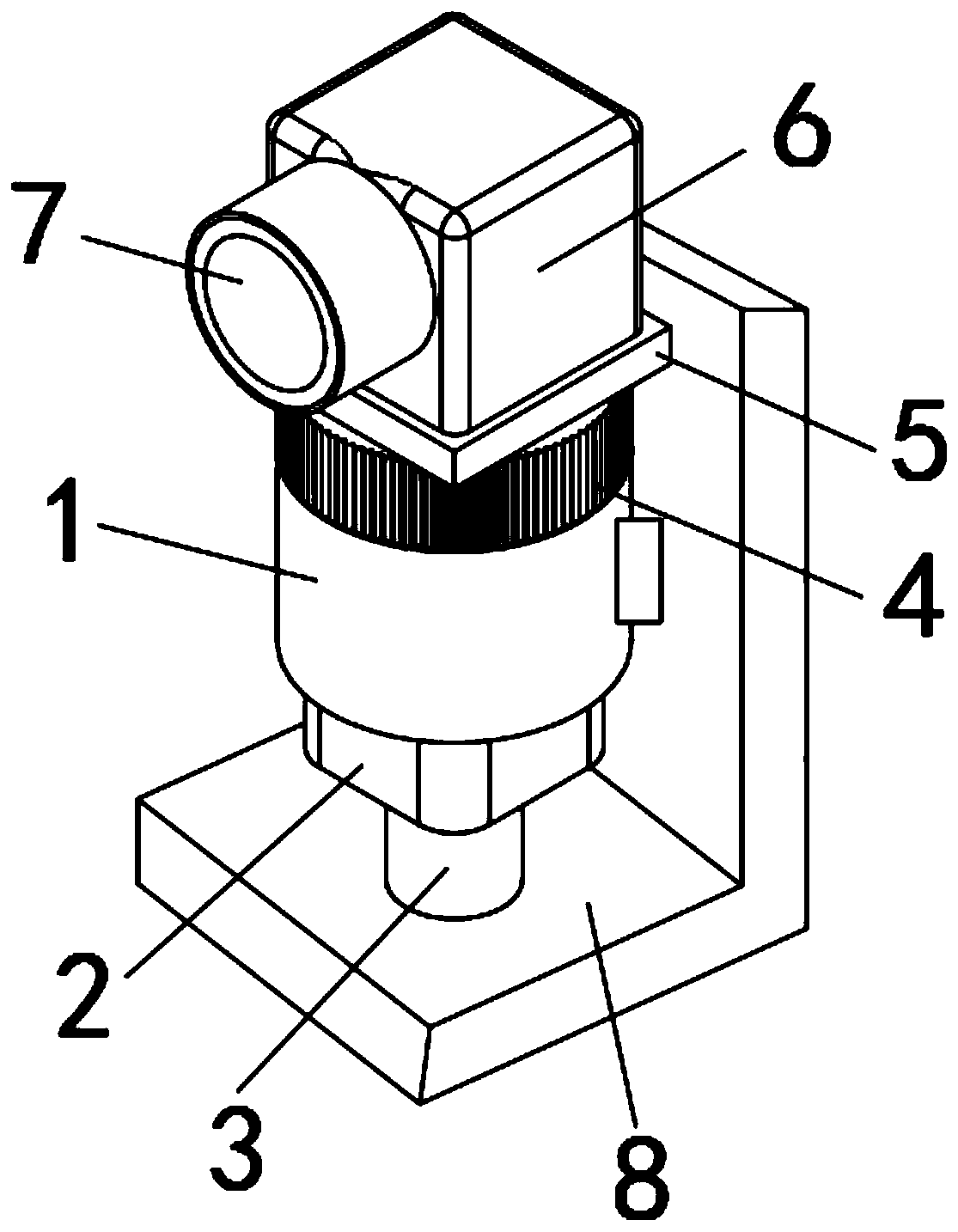
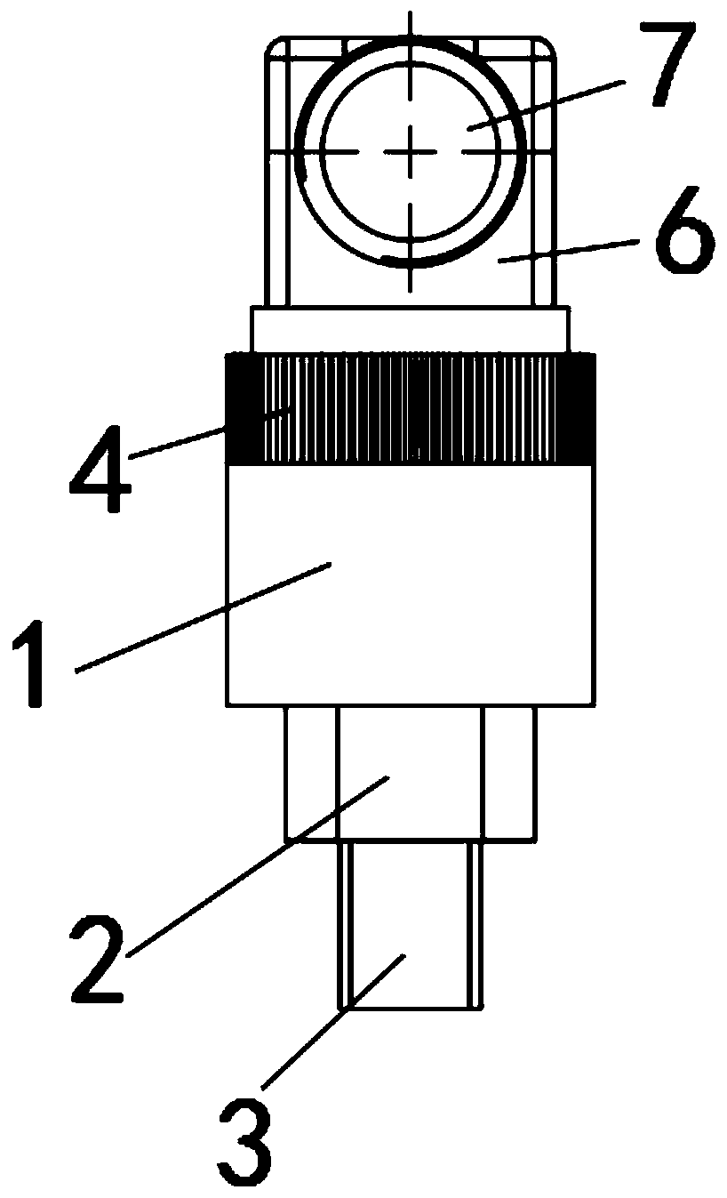
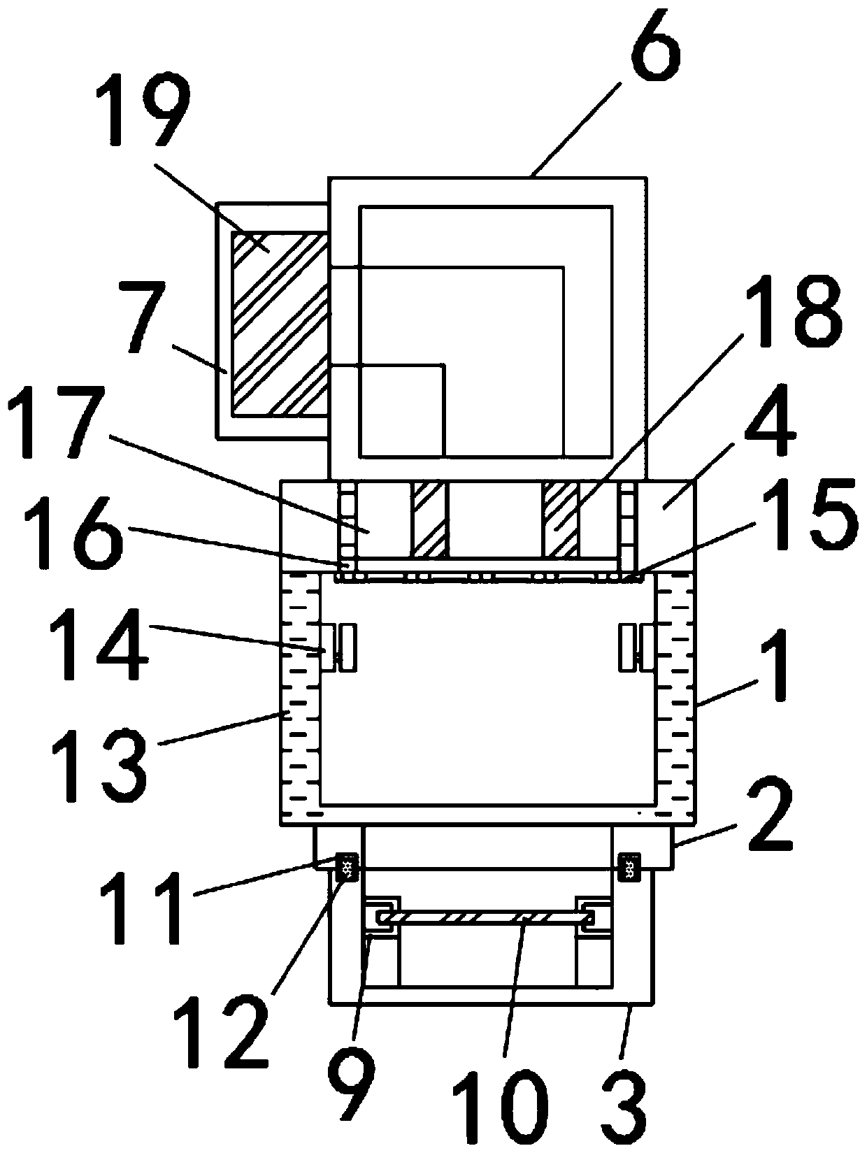
[0038] see Figure 1-7 As shown, an elastic pressure sensor probe structure includes a detection housing 1, a base 2 is installed on the lower side of the detection housing 1, and a pressure port 3 is installed on the lower side of the base 2, and the upper periphery of the detection housing 1 A threaded sleeve 4 is installed, and a spacer 5 is installed on the top of the detection housing 1. A wire harness chamber 6 is installed on the upper part of the spacer 5, and a wire inlet barrel 7 is installed on the side wall of t...


PUM


Abstract

The invention discloses an elastic pressure sensor probe structure. The structure comprises a detection shell. A lower side of the detection shell is provided with a pedestal. The lower side of the pedestal is provided with a pressure port. A periphery of an upper end of the detection shell is provided with a threaded sleeve. The upper portion of a cushion block is provided with a wire harness chamber. The side wall of the wire harness chamber is provided with an inlet wire cylinder. Through arranging an installation support, the whole probe structure is fixed so that the whole probe structurecan be conveniently installed and simultaneously the probe structure can be protected. Through arranging a diaphragm fixing rack, a first clamping plate and a second clamping plate are used to fix adiaphragm installed in a later period so that a problem that a traditional diaphragm can not be dismounted after being installed is solved, and the diaphragm can be conveniently replaced and installed. Through arranging a heat dissipation inner sleeve in an inner edge of the detection shell, a bottom of the detection shell has a good heat insulation effect and a good heat dissipation effect, and the service life of the probe structure under a high temperature condition is prolonged.

Description

technical field [0001] The invention relates to the field of sensors, in particular to an elastic pressure sensor probe structure. Background technique [0002] Pressure sensor is the most commonly used sensor in industrial practice. It is widely used in various industrial automatic control environments, involving water conservancy and hydropower, railway transportation, intelligent buildings, production automatic control, aerospace, military industry, petrochemical, oil wells, electric power, ships, machine tools , pipelines and many other industries, the following is a brief introduction to the principles and applications of some commonly used sensors, as well as medical pressure sensors, which are the most widely used sensors. Traditional pressure sensors are mainly based on mechanical structural devices, and the deformation of elastic elements is used to indicate pressure. However, this structure is large in size and heavy in weight, and cannot provide electrical output....

Claims


Application Information

Patent Timeline
Patent Type & Authority Patents(China)
IPC IPC(8): G01L19/06G01L19/14
Inventor 刘威
Owner 苏州新意达仪器科技有限公司
Learn More