Transmission device for air conditioner

A transmission device, air conditioner technology, applied in transmission systems, digital transmission systems, refrigerators, etc., can solve problems such as inability to communicate and transmission systems to work.

Inactive Publication Date: 2003-01-15
DAIKIN IND LTD
View PDF1 Cites 0 Cited by
  • Summary
  • Abstract
  • Description
  • Claims
  • Application Information

AI Technical Summary

Problems solved by technology

[0008] However, when the communication line in one part of the transmission system of the air conditioner is short-circuited or disconnected, the communication cannot be performed in that part.
As a result, communication cannot be performed between each control device and the centralized control device, resulting in a problem that the entire transmission system cannot work

Method used


Image

  • Transmission device for air conditioner
  • Transmission device for air conditioner
  • Transmission device for air conditioner

Examples


Embodiment 1

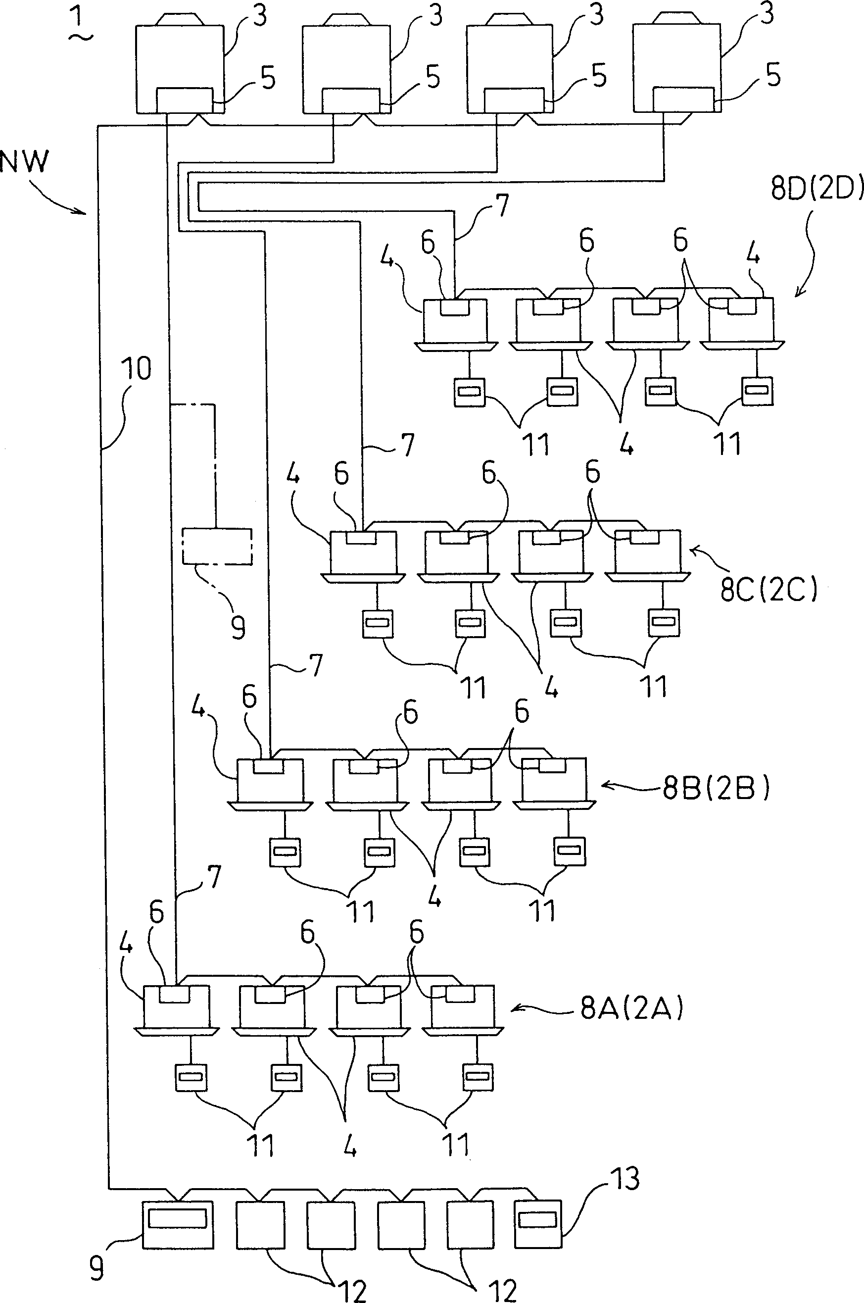
[0061] image 3 Shown is the transmission system of the air conditioner 1 according to the first aspect, the fifth aspect, and the sixth aspect of the present invention. The air conditioner 1 is provided with a plurality of refrigerant cycle groups 2A, 2B, 2C, and 2D. exist image 3 Among them, the refrigerant cycle groups 2A, 2B, 2C, and 2D are composed of four groups. These four refrigerant circulation groups 2A, 2B, 2C, 2D are respectively connected to an outdoor device 3 through refrigerant piping not shown in the figure, and the four indoor devices 4, 4, ... are connected in parallel Way to connect composition.

[0062]The above-mentioned outdoor device 3 is a heat source side device including a compressor not shown in the figure, a four-way switching valve, a heat exchanger equipped with a fan, and an outdoor electric expansion valve. In addition, the above-mentioned indoor unit 4 is a use-side unit equipped with an indoor electric expansion valve not shown in the fi...

Embodiment 2

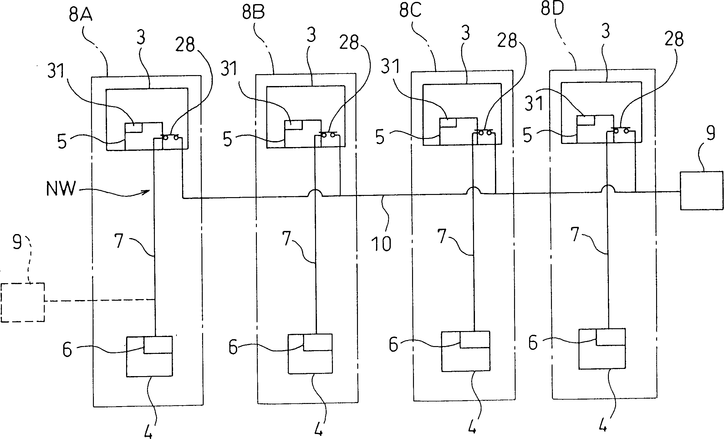
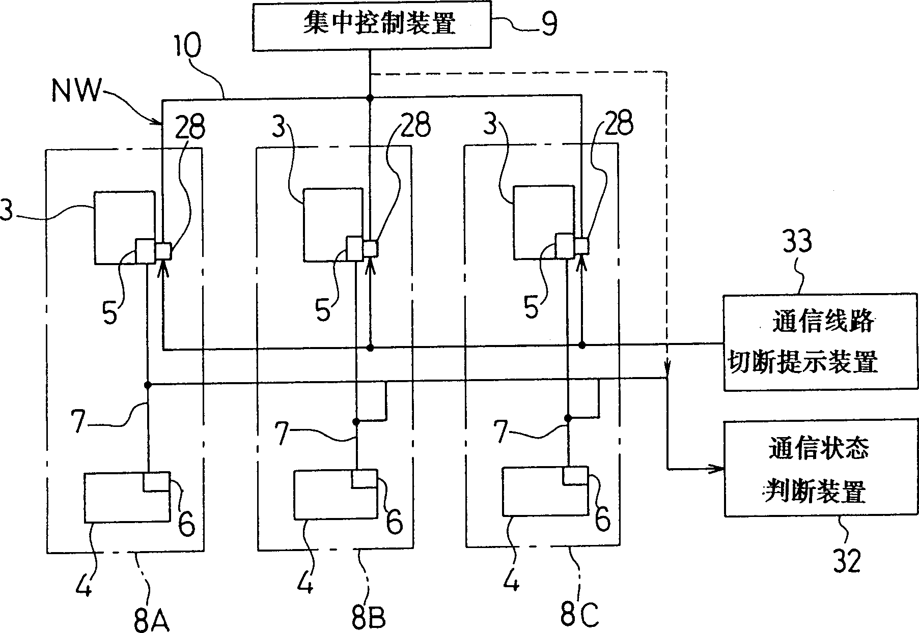
[0132] Figure 7 and Figure 8 Shown is Embodiment 2 related to the fifth to eighth aspects of the present invention. Figure 7 is the same as that of Example 1 image 3 In the corresponding transmission system diagram, for the sake of simplicity, only three control groups 8A, 8B, 8C are drawn. In addition, the first control group 8A and the second control group 8B have one indoor device 4 ; the third control group 8C has two indoor devices 4 , 4 .

[0133] In addition, the circuit structures of the outdoor devices 5 and the like of the above-mentioned control groups 8A, 8B, and 8C are the same as Figure 4 The circuit shown is the same.

[0134] Therefore, the feature of present embodiment 2 is to be provided with: communication state judging device 32, is used for judging the communication state of above-mentioned this system communication line 7 and centralized communication line 10; When the output of the device 32 encounters a short circuit in the communication line ...


PUM


Abstract

A plurality of control groups (8A, 8B, ---) are provided which comprise outdoor control units (5) and indoor control units (6) connected to each other by self-system communication lines (7) so as to enable transmission and reception of signals. The respective control units (5, 5, ---) are connected to one another by an integrated line (10) so as to enable transmission and reception. In the respective control units (5, 5, ---), the self-system communication lines (7) are connected to the integrated line (10) to constitute a single transmission network (NW). Further, the transmission network (NW) is connected to a centralized controller (9) which serves to perform centralized control of outdoor units (3, 3, ---) and indoor units (4, 4, ---). Also, relays (28a, 28b) are provided which serve to establish and cut off continuity between the self-system communication lines (7) and the integrated line (10).

Description

technical field [0001] The present invention relates to a transmission device of an air conditioner, in particular to the improvement of the transmission device which can perform operation control between a heat source side control device and a use side control device and which can be centrally controlled by a centralized control device. Background technique [0002] In the prior art, as shown in JP-A-59-210249, an outdoor unit and an indoor unit in an air conditioner are connected through refrigerant piping, and an outdoor control unit for controlling the outdoor unit and an outdoor control unit for controlling the outdoor unit The indoor control device controlling the indoor device is connected through the communication line of this system. Therefore, the above-mentioned outdoor control device and the indoor control device constitute a control group by transmitting and receiving various control signals such as operation signals and mode signals. [0003] In addition, the ...

Claims


Application Information

Patent Timeline
Patent Type & Authority Patents(China)
IPC IPC(8): F24F11/00
CPCF24F2011/0067F24F11/006H04L12/403H04L2012/285F24F11/0009F25B2400/075H04L12/2816H04L12/2838F24F11/30F24F11/62F24F11/54
Inventor 冈野贵史内田耕慈镰房功二川上久寿曾我部正晴田中修
Owner DAIKIN IND LTD
Why Eureka
Try Eureka