Hot-film wind speed sensing unit and sensor based on HTCC technology and preparation method of sensing unit
A wind speed sensor and wind speed sensing technology, applied in the direction of using thermal variables to measure fluid speed, etc., can solve the problems of being susceptible to wind direction interference, low measurement accuracy of wind speed sensors, etc., to solve the problem of unstable airflow, little influence of wind direction, and easy integration Effect
- Summary
- Abstract
- Description
- Claims
- Application Information
AI Technical Summary
Problems solved by technology
Method used
Image
Examples
specific Embodiment approach 1
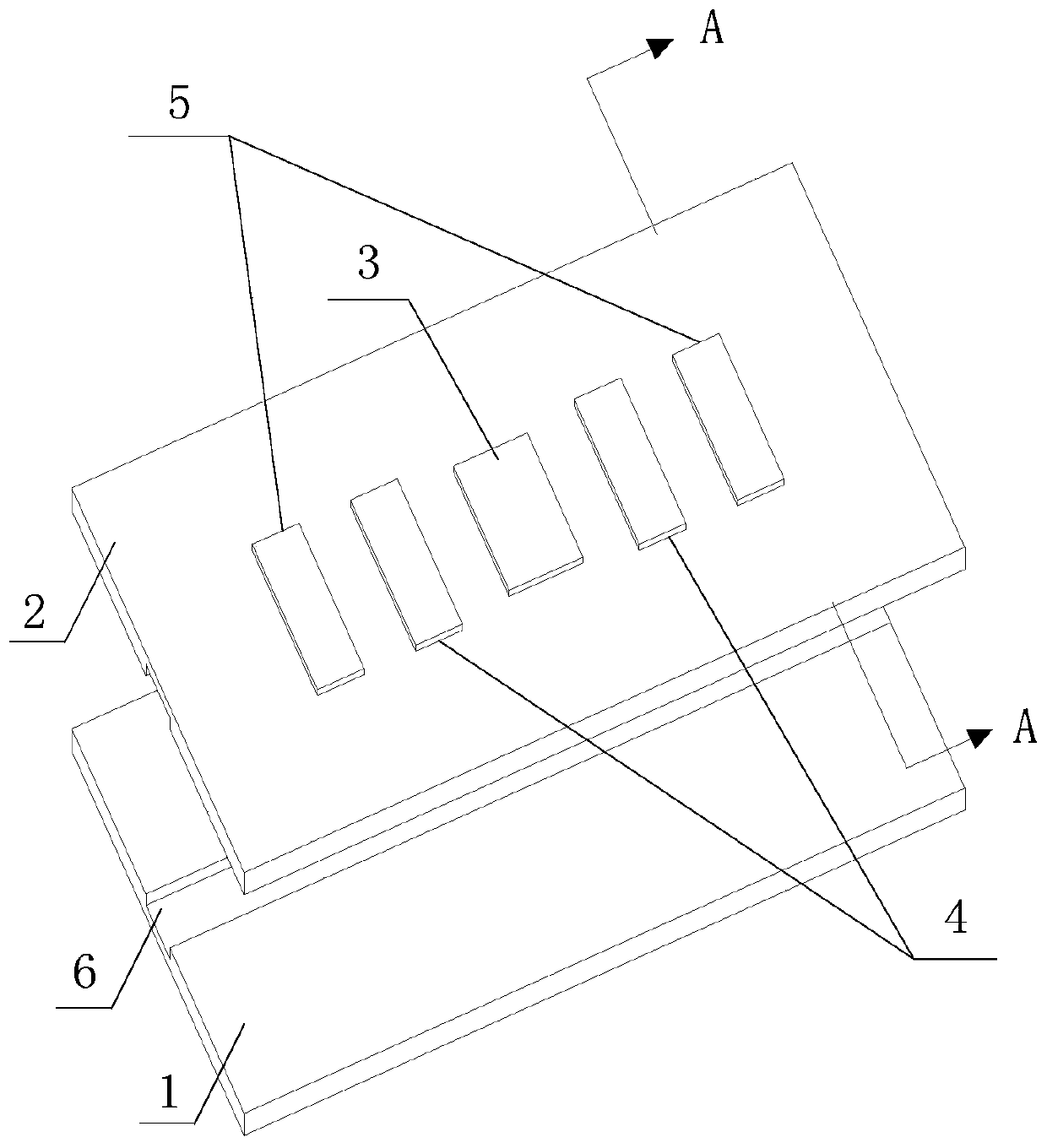
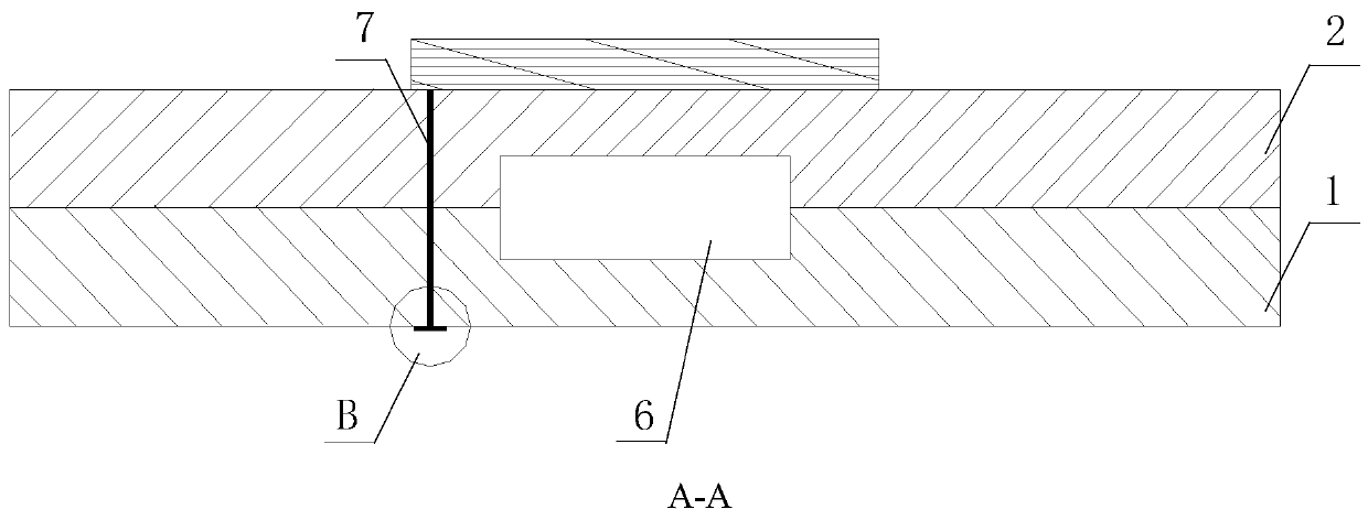
[0043] Specific implementation mode one: refer to Figure 1 to Figure 3 Specifically explain this embodiment, the hot-film wind speed sensing unit based on HTCC (high temperature co-fired ceramics) process described in this embodiment includes: two ceramic substrates and five resistors, the two ceramic substrates are respectively the upper The substrate 2 and the lower substrate 1, the five resistors are: one heating resistor 3, two control resistors 4 and two temperature sensing resistors 5;
[0044] The two substrates are stacked and fixed, and the five resistors are fixed on the upper surface of the upper substrate 2 along a straight line,
[0045] The two control resistors 4 are distributed on both sides of the heating resistor 3 in a mirror image structure, and the two temperature sensing resistors 5 are distributed outside the two control resistors 4 in a mirror image structure.
[0046] The junction of the two substrates is provided with a diversion groove 6 with openi...
specific Embodiment approach 2
[0050] Specific implementation mode two: refer to Figure 4 Specifically explain this embodiment, the hot-film wind speed sensor based on HTCC technology described in this embodiment includes: two substrates and 2n+1 resistors, 2n+1 resistors include: a heating resistor 3 and n pairs of resistors Yes, each pair of resistors includes a control resistor 4 and a temperature sensing resistor 5, n is a positive integer;
[0051] In this embodiment, n=8, under the condition that there are 8 pairs of resistance pairs and the upper surface of the upper substrate 2 is a rectangular structure, the structure of the sensor is as follows:
[0052] The two substrates are stacked and fixed, and the 17 resistors are all fixed on the upper surface of the upper substrate 2,
[0053] The heating resistor 3 is located at the center of the upper surface of the upper substrate 2, and 8 pairs of resistors are distributed around the heating resistor 3. The 8 pairs of resistors are paired in pairs to...
specific Embodiment approach 3
[0059] Specific embodiment three: this embodiment is the preparation method of the sensing unit described in specific embodiment one, and the specific preparation method is as follows:
[0060] Use a punching machine to make via holes 7 on the two substrates respectively,
[0061] Fill the via holes 7 of the upper substrate 2 with platinum paste by screen printing, and print five resistors on the upper surface of the upper substrate 2 respectively,
[0062] Fill the via holes 7 of the lower substrate 1 with platinum paste, and print a lead-out 71 at the outlet of each via hole 7 on the lower surface of the lower substrate 1,
[0063] Use carbon paste to print flow guide lines on the upper surface of the lower substrate 1, wherein the thickness of the carbon paste is 20 μm to 100 μm,
[0064] Lay the two substrates together so that the arrangement direction of the five resistors is consistent with the direction of the current guide line, and the via holes 7 of the upper substr...
PUM
 Abstract
Description
Claims
Application Information
 - R&D
- Intellectual Property
- Life Sciences
- Materials
- Tech Scout
- Unparalleled Data Quality
- Higher Quality Content
- 60% Fewer Hallucinations
Browse by: Latest US Patents, China's latest patents, Technical Efficacy Thesaurus, Application Domain, Technology Topic, Popular Technical Reports.
© 2025 PatSnap. All rights reserved.Legal|Privacy policy|Modern Slavery Act Transparency Statement|Sitemap|About US| Contact US: help@patsnap.com


