Eureka AIR delivers breakthrough ideas for toughest innovation challenges, trusted by R&D personnel around the world.

Rotary remote controller for lifting platform and control method thereof

A lifting platform and remote control technology, applied in the field of hand controls, can solve the problems of not adapting to the structure of the remote control, inconvenient use, non-removable encoders and shells, etc., and achieve the effects of convenient use, firm installation and stable connection.

Pending Publication Date: 2019-06-18
ZHEJIANG JIECHANG LINEAR MOTION TECH
View PDF6 Cites 1 Cited by
  • Summary
  • Abstract
  • Description
  • Claims
  • Application Information

AI Technical Summary

Problems solved by technology

[0002] At present, the encoder in the remote controller and the shell of the control encoder are usually connected by plugging or riveting. The shells are not detachable, so it is not suitable for the structure of the remote control that needs to replace the battery

Method used


Image

  • Rotary remote controller for lifting platform and control method thereof
  • Rotary remote controller for lifting platform and control method thereof
  • Rotary remote controller for lifting platform and control method thereof

Examples


Embodiment 1

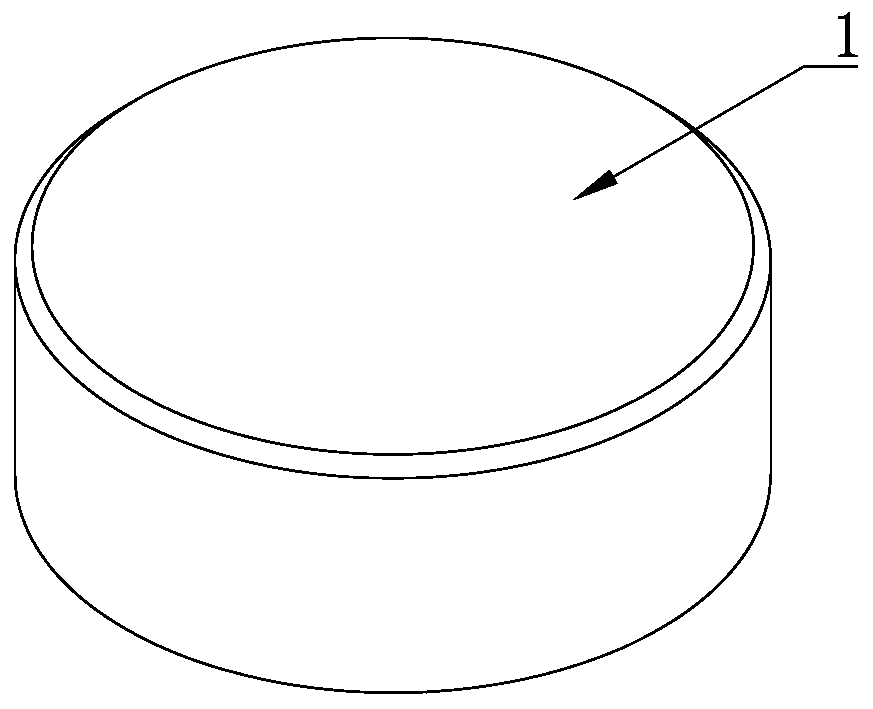
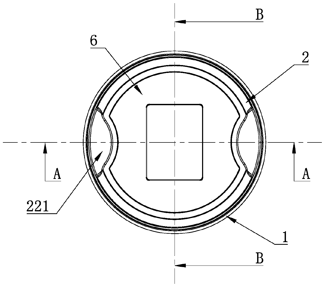
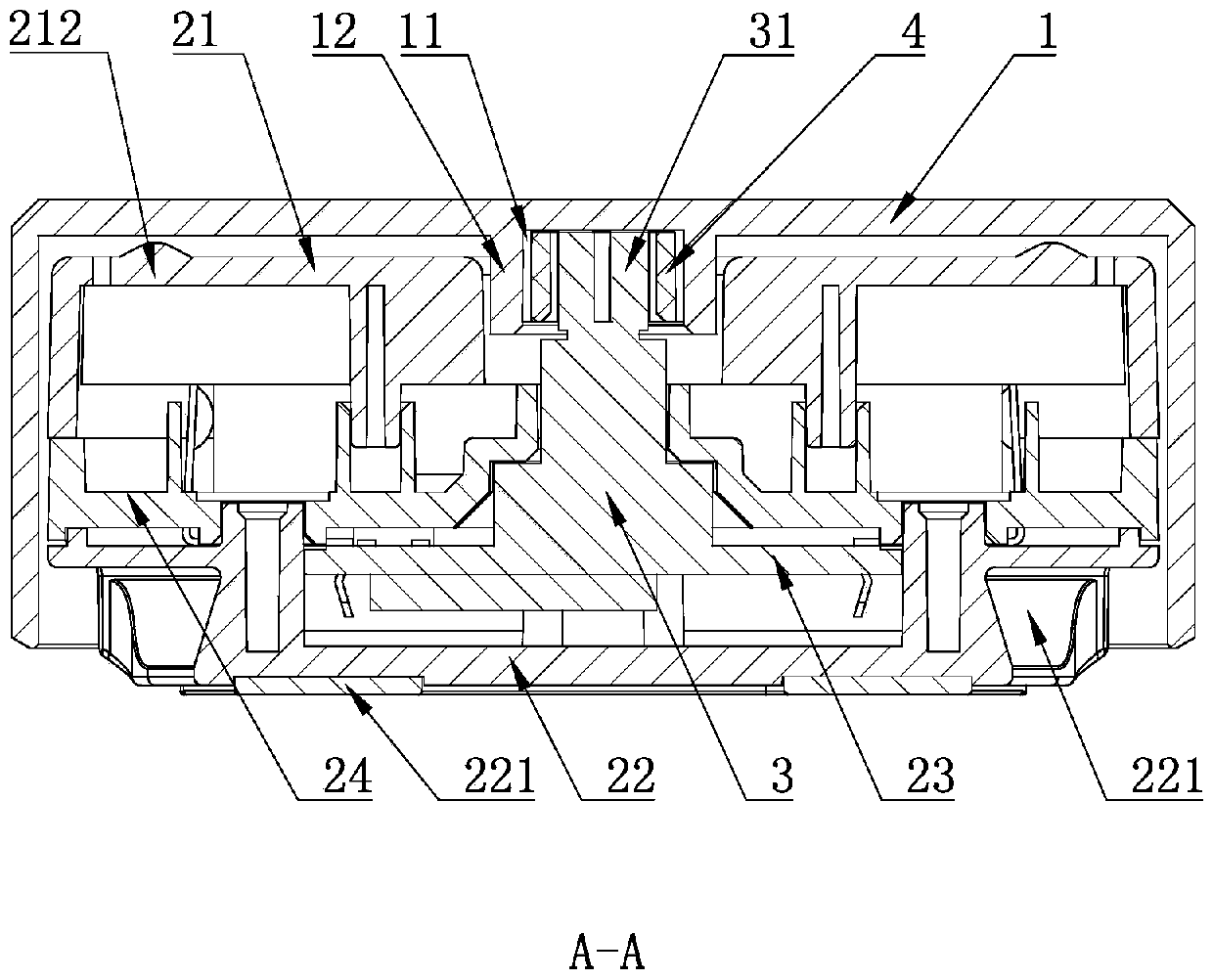
[0030] A rotary remote control for a lifting platform, comprising a base 2, an encoder 3 arranged on the base 2 and a knob 1 that is rotationally connected to the base 2 through the encoder 3, the encoder 3 includes an input shaft 31, and the connection between the input shaft 31 and the knob 1 There is an elastic connecting piece 4 connected between them, and the elastic connecting piece 4 is respectively in interference fit with the input shaft 31 and the knob 1, and the knob 1 connected to the encoder 3 can be rotated clockwise or counterclockwise on the base 2, or the knob can be pressed 1.

[0031] The elastic connector 4 is interference-fitted with the end of the input shaft 31, and the elastic connector 4 and the knob 1 are interference-fitted, so that the elastic connector 4 and the encoder 3 are detachably connected, while the elastic connector 4 and the knob 1 are detachably connected; when in use, because under the action of elastic force, the elastic connecting pie...

Embodiment 2

[0038]A control method for a rotating remote controller of a lifting platform. The rotating remote controller of the lifting platform includes a tact switch 7 connected to a circuit board 23, a wireless transmitting and receiving device 8, a chip and a vibration motor 9. In this embodiment, the wireless transmitting and receiving The device 8 is a 2.4G receiving box, and the steps of the control method are as follows,

[0039] The first step, code matching: separate the knob 1 and the base 2, and then press the tact switch 7 to make the tact switch 7 and the wireless transmitting and receiving device 8 perform code matching, so that the tact switch 7 and the wireless transmitting and receiving device 8 Be in the same frequency band, so that the remote control can control the lifting controller on the lifting platform through the wireless transmitting and receiving device 8, and then control the lifting of the lifting platform, and finally install the knob 1 on the base 2;

[0...


PUM


Abstract

The invention discloses a rotary remote controller for a lifting platform. The remote controller includes a base, an encoder arranged on the base and a turn button in rotation connection with the basethrough the encoder, wherein the encoder includes an input shaft, an elastic connection member is connected between the input shaft and the turn button, the elastic connection member is in interference fit with the input shaft and the turn button, the elastic connection member is in interference fit with the encoder and the turn button, the turn button is prevented from spontaneously falling offthe encoder while the turn button is turned and pressed, so connection between the encoder and the turn button is made to be more stable. When a cell is replaced, only pulling the turn button with force from the base is needed to replace the cell, requirements for firmly mounting the remote controller and replacing the cell can be both met through the structure, and the remote controller is more convenient to use. The invention further provides a control method of the rotary remote controller for the lifting platform, and the control method is more convenient to use.

Description

technical field [0001] The invention belongs to the field of hand controllers, and in particular relates to a rotary remote controller for a lifting platform and a control method thereof. Background technique [0002] At present, the encoder in the remote controller and the shell of the control encoder are usually connected by plugging or riveting. The shells cannot be disassembled, and it is not suitable for the structure of the remote control that needs to replace the battery. Contents of the invention [0003] The technical problem to be solved by the present invention is to provide a rotating remote controller for a lifting platform that is convenient for battery replacement. [0004] In order to solve the above technical problems, the present invention adopts the following technical solutions: a rotary remote control for lifting platforms, including a base, an encoder arranged on the base, and a knob that is rotationally connected to the base through the encoder, the...

Claims


Application Information

Patent Timeline
Patent Type & Authority Applications(China)
IPC IPC(8): G08C17/02
Inventor 周少萍
Owner ZHEJIANG JIECHANG LINEAR MOTION TECH
Why Eureka
Eureka Blog
Learn More