Time synchronization precision detection system

A technology of time synchronization accuracy and time synchronization, which is applied to components of TV systems, components of color TVs, TVs, etc., can solve problems such as inability to compare timestamp information, and achieve the effect of improving detection efficiency

Active Publication Date: 2019-06-18
CHANGCHUN INST OF OPTICS FINE MECHANICS & PHYSICS CHINESE ACAD OF SCI
View PDF5 Cites 5 Cited by
  • Summary
  • Abstract
  • Description
  • Claims
  • Application Information

AI Technical Summary

Problems solved by technology

[0003] The present invention solves the problem that the external detection equipment of the existing imaging unit cannot generate the comparison time stamp information without outputting the start signal of the exposure time. Provide a detection system for time synchronization accuracy

Method used


Image

  • Time synchronization precision detection system
  • Time synchronization precision detection system
  • Time synchronization precision detection system

Examples


specific Embodiment approach 1

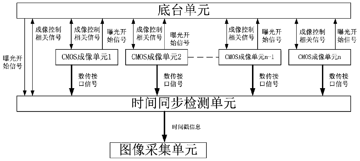
[0018] Specific implementation mode 1. Combination Figure 1 to Figure 4 To illustrate this embodiment, the detection system for time synchronization accuracy includes n groups of CMOS imaging units, a base unit, a time synchronization detection unit, and an image acquisition unit. The time synchronization detection unit generates imaging control related signals, which are sent to n groups of CMOS imaging through the base unit; the reset signal output by the time synchronization detection unit is divided into n+1 delayed timing reset signals in the base unit, n+1 The timing reset signal of the road delay resets the time synchronization detection unit and the time stamp signal to n groups of CMOS imaging units respectively, and the time synchronization detection unit and n groups of CMOS imaging units perform microsecond counting according to the clock;

[0019] The time synchronization detection unit outputs line cycle signals and GPS signals and transmits them to n groups of ...


PUM


Abstract

The invention discloses a time synchronization precision detection system. The invention relates to a time synchronization precision detection system. The objective of the invention is to solve the problem that an external detection device of an existing imaging unit outputs no initial signal at an exposure moment. According to the method, timestamp information cannot be compared, meanwhile, the problems of delay output by an initial signal at the exposure moment from the interior of an imaging unit, delay sent into external detection equipment and the like need to be tested, and the method comprises a bottom table unit, a time synchronization detection unit, an image acquisition unit and n groups of CMOS imaging units; Time stamp information is generated in the imaging unit, and the timestamp information does not need to be transmitted back and forth; Based on a simplified White rabbit protocol, the time synchronization precision is detected by comparing the timestamp information ofthe crystal with higher frequency stability.

Description

technical field [0001] The invention relates to a time synchronization accuracy detection system, in particular to a high-precision time synchronization accuracy detection system. Background technique [0002] In the existing time synchronization method, the camera controller usually calculates the line period according to the attitude-orbit information, and then sends it to the imaging unit; the imaging unit generates the corresponding timing control signal according to the received line period, and at the same time generates the start signal of the exposure time Send to the camera controller; the camera controller generates the time stamp information of the shooting time according to the received start signal of the exposure time, and then sends it to the imaging unit through the serial interface; the imaging unit then uses the time stamp information of the shooting time as auxiliary data is sent together with the image data. If the time stamp information is generated ins...

Claims


Application Information

Patent Timeline
Patent Type & Authority Applications(China)
IPC IPC(8): H04N17/00H04N5/374H04N5/359H04N5/232
Inventor 余达刘金国孔德柱梅贵刘春香石俊霞袁航飞
Owner CHANGCHUN INST OF OPTICS FINE MECHANICS & PHYSICS CHINESE ACAD OF SCI
Why Eureka
Try Eureka