Automatic detecting and correcting device for light intensity of optical projector

An automatic detection, light-mechanical technology, applied in the field of 3D printing, can solve the problems of affecting the work effect, inconvenient operation, printing failure, etc., and achieve the effect of improving the printing success rate, prolonging the service life and reducing the workload

Pending Publication Date: 2019-06-21
福建国锐中科光电有限公司
View PDF0 Cites 0 Cited by
  • Summary
  • Abstract
  • Description
  • Claims
  • Application Information

AI Technical Summary

Problems solved by technology

[0002] At present, the way of artificially identifying the light intensity and adjusting it manually in the market is inconvenient to operate and will bring human error
Another way to let the attenuation of the LED / backlight light continue to blur the image
[0003] However, in the application of DLP series optical machines in 3D printing, there are relatively high requirements for light intensity. It is necessary to ensure that the LED backlight is at a specific wavelength and a stable illuminance at a specific wavelength. If these two conditions cannot be met, it will cause The failure of the 3D printing work; and the requirement for the consistency of the light intensity of the projection surface of the entire optical machine is high, otherwise there may be differences in the consistency of product printing
Therefore, in the special 3D printing equipment, it is necessary to focus on controlling these parameters; secondly, during the continuous use of the DLP light machine, with the attenuation of the LED backlight, the light intensity of the light machine will also slowly decay, which will affect the working effect ;Third, during the use of DLP series 3D printers, there may be accidental adjustments that cause the light output path of the optical machine to be partially blocked by gray layers, sundries, etc., destroying the integrity of the entire optical path, and resulting in printing failure.

Method used


Image

  • Automatic detecting and correcting device for light intensity of optical projector
  • Automatic detecting and correcting device for light intensity of optical projector
  • Automatic detecting and correcting device for light intensity of optical projector

Examples


specific Embodiment approach

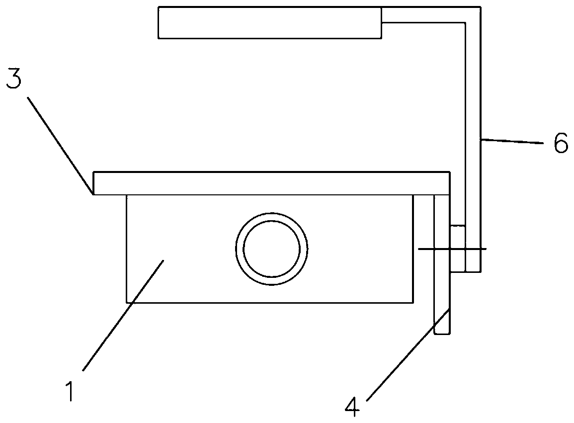
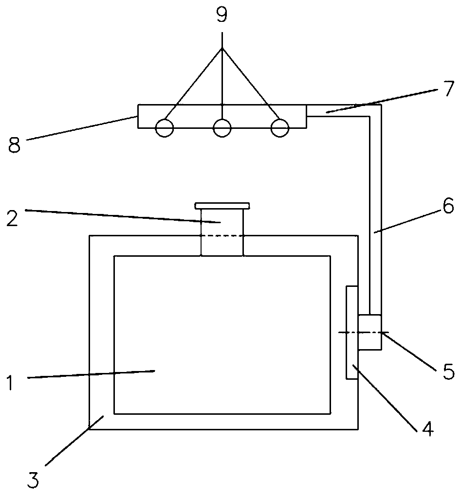
[0020] like figure 1 , figure 2 As shown, it includes an optical machine 1, and the top of the optical machine 1 is provided with a light outlet 2; the optical machine rear cover 3 of the optical machine 1 extends the optical machine mechanism fixing plate 4 to the side of the optical machine 1, and is characterized in that: The fixed plate 4 of the optical mechanical mechanism is provided with a rotating shaft 5; the rotating shaft 5 is fixedly connected with a measuring mechanism 6, and the other end of the measuring mechanism 6 is connected with a working panel 8 through a rotating connecting rod 7; the working When the panel 8 is working, it is rotated by the rotating shaft 5 to the illuminated area above the light outlet 2, and when it is not in the working state, it is rotated by the rotating shaft 5 to the non-illuminated area; there are several sensing devices 9 dotted on the lower surface of the working panel 8; The rotating shaft 5 is connected with the motor, and ...


PUM


Abstract

The invention discloses an automatic detecting and correcting device for the light intensity of an optical projector. The automatic detecting and correcting device comprises the optical projector, anda light outlet is formed in the top of the optical projector; and an optical projector rear cover plate of the optical projector is provided with an optical projector mechanism fixing plate towards the side face of the optical projector in an extending mode. The automatic detecting and correcting device is characterized in that a rotating shaft is arranged on the optical projector mechanism fixing plate; a measuring mechanism is fixedly connected to the rotating shaft, and the other end of the measuring mechanism is connected with a working panel through a rotating connecting rod; when working, the working panel is rotated into an illumination area above the light outlet by the rotating shaft and rotated to a non-illumination area by the rotating shaft when in a non-working state; and a plurality of induction devices are distributed on the lower surface of the working panel in a dotted mode. The automatic detecting and correcting device automatically measures the light intensity of the optical projector after the optical projector is started, the actual illumination intensity can be effectively measured, and the illumination intensity of the optical projector is adjusted to meet the demands by changing the current magnitude of the optical projector; and when an optical path of the optical projector is damaged, a worker is reminded to conduct timely processing, operation is convenient, and the service life of the optical projector is effectively prolonged.

Description

technical field [0001] The invention relates to the field of 3D printing, in particular to an optical-mechanical light intensity automatic detection and correction device. Background technique [0002] Currently on the market, the method of artificially identifying the light intensity and manually adjusting it is inconvenient to operate and will cause human errors. Another kind of letting go of the attenuation of the LED / backlight, causing the image to continue to blur. [0003] However, in the application of DLP series optical machines in 3D printing, there are relatively high requirements for light intensity. It is necessary to ensure that the LED backlight is at a specific wavelength and a stable illuminance at a specific wavelength. If these two conditions cannot be met, it will cause The failure of 3D printing work; and the requirement for the consistency of light intensity on the projection surface of the entire optical machine is high, otherwise there may be differen...

Claims


Application Information

Patent Timeline
Patent Type & Authority Applications(China)
IPC IPC(8): B29C64/286B29C64/386B29C64/393B33Y30/00B33Y50/00B33Y50/02
Inventor 刘永德林友华连善伟张震奇刘永明张梓涵
Owner 福建国锐中科光电有限公司
Why Eureka
Try Eureka