
Gear shifting hand rocker

A hand crank and shifting mechanism technology, which is applied in the field of hand cranks, can solve the problems of large volume, unstable shifting, and high cost of the hand crank, and achieve the effects of small overall size, stable shifting, and low cost

Pending Publication Date: 2019-06-21
九牧智能厨卫(安徽)有限公司
View PDF4 Cites 3 Cited by
  • Summary
  • Abstract
  • Description
  • Claims
  • Application Information

AI Technical Summary

Problems solved by technology

This can certainly solve the problem of unstable shifting of the traditional gearshift hand crank, but due to the dual-axis structure, the entire hand crank has a larger volume, more accessories, and higher cost

Method used


Image

  • Gear shifting hand rocker
  • Gear shifting hand rocker
  • Gear shifting hand rocker

Examples


Embodiment Construction

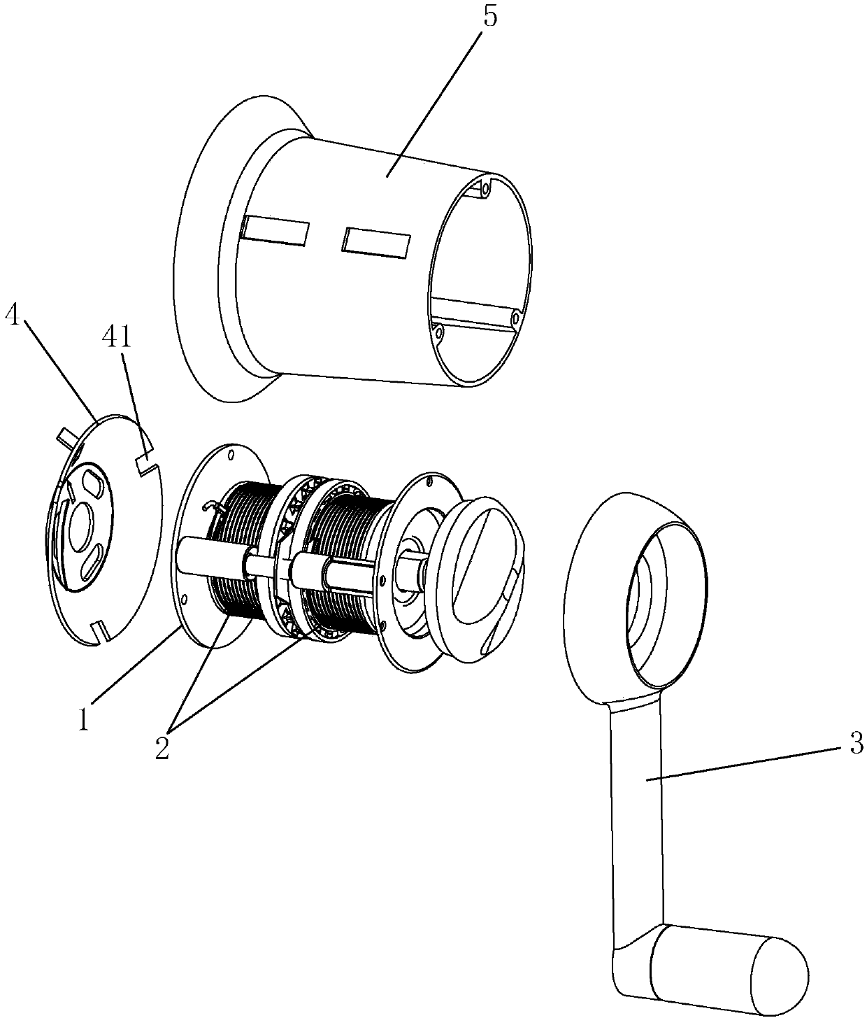
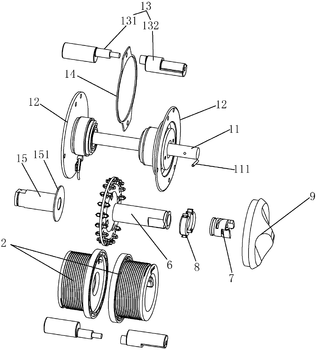
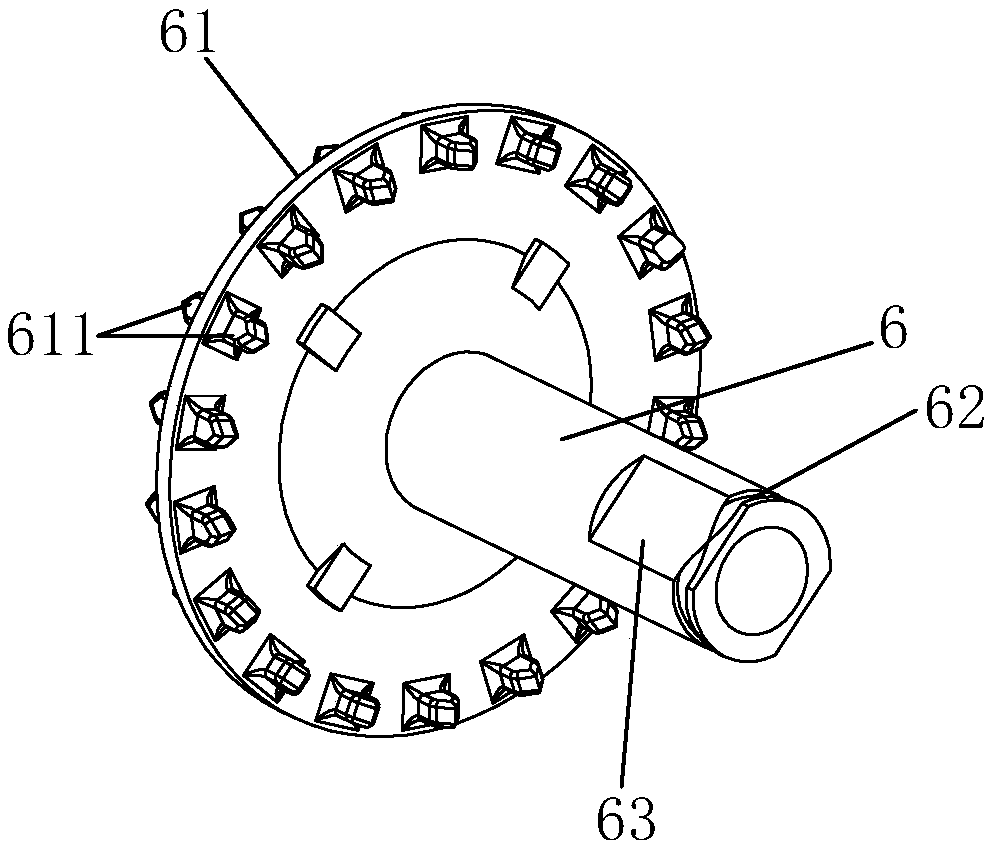
[0034] Examples, see Figure 1-Figure 13 As shown, a shift hand crank of the present invention includes a fixed body 1, two winding wheels 2, a handle 3 and a shift mechanism, and the shift mechanism includes a hollow push-pull part 6, and the push-pull part 6 is provided with The clip 61; the fixed body 1 has a support shaft 11, the push-pull part 6 is rotatably sleeved on the support shaft 11, and is connected to the handle 3; the two winding wheels 2 are respectively rotatably sleeved on the support shaft 11 or The push-pull part 6 or the sleeve provided on the support shaft 11;

[0035] In this embodiment, the clamping member 61 fits between the two reels 2, and the clamping member 61 is specifically a disc structure, and the two ends of the clamping member 61 are respectively distributed with several protrusions along the circumferential direction. Teeth 611 , the opposite inner end surfaces of the two reels 2 are respectively distributed along the circumferential direct...


PUM


Abstract

The invention discloses a gear shifting hand rocker. The hand rocker comprises a fixing body, two wire winding wheels, a handle and a gear shifting mechanism, the gear shifting mechanism comprises a hollow push pull member, the push pull member is provided with a clamping member, the fixing body is provided with a supporting shaft, the push pull member rotatably sleeves the supporting shaft and isconnected with the handle, the two wire winding wheels rotatably sleeve a\ shaft sleeve which is arranged on the supporting shaft, the push pull member or the supporting shaft, and the push pull member can be pushed or pulled to move in the axial direction of the push pull member to allow the clamping member of the push pull member to clamp one of the two wire winding wheels. The push pull membersleeves the supporting shaft, gear shifting operation is achieved through the axial moving of the push pull member to allow the supporting shaft to be taken as a primary load bearing carrier to prevent movement in the axial direction, so that the gear shifting of the hand rocker is stable, the vibration is faint, there exists no noise, and the service life of the hand rocker is longer.

Description

technical field [0001] The invention relates to a hand crank, in particular to a shift hand crank. Background technique [0002] The traditional gear shifter generally has only one main shaft, and the main shaft is equipped with a gear pin. By pushing and pulling the main shaft, the gear pin on the main shaft is matched with the cross gear groove of the shift fork, so as to achieve the shifting of the gear position. Purpose. Although this kind of hand crank for gear shifting is easy to operate, because the gear shift is realized through the axial movement of the entire main shaft, the main shaft and the handle must move when shifting gears, resulting in a relatively large vibration of the hand crank during the gear shifting process. Violent and noisy, the hand crank is easily damaged and has a short service life. For this reason, there is a dual-shaft gear push-pull gearshift hand crank in the prior art, which is additionally provided with a transmission shaft, and uses th...

Claims


Application Information

Patent Timeline
Patent Type & Authority Applications(China)
IPC IPC(8): B66D1/06B66D1/14B66D1/26B66D1/28D06F57/00
Inventor 林孝发林孝山梅林朱亚熙莫忠才
Owner 九牧智能厨卫(安徽)有限公司
Learn More