
Self-locking rope winch

A self-locking and rope technology, applied in the direction of hoisting device, spring mechanism, etc., can solve the problems of high labor cost, low labor efficiency, short service life, etc., and achieve high safety performance, high transportation efficiency and simple structure. Effect

Pending Publication Date: 2019-06-21
WEIFANG WANREN ELECTROMECHANICAL TECH
View PDF0 Cites 0 Cited by
  • Summary
  • Abstract
  • Description
  • Claims
  • Application Information

AI Technical Summary

Problems solved by technology

[0002] At present, there are many load-carrying devices with lifting functions, such as cranes, hoisting machinery, cranes, lifting pulley blocks, etc. These lifting load-carrying devices need to be used in specific occasions, and sometimes due to environmental conditions, the existing lifting load-carrying devices cannot be used.
When it is necessary to move heavy objects over long distances, most of the above-mentioned lifting equipment is used for transportation, and its labor efficiency is low
For example, it is necessary to transport heavy objects from the bottom of the mountain to the mountain, and tools such as cable cars are required. The labor cost is high and the efficiency is low. At present, there is no special tool that is simple and can transport heavy objects vertically or horizontally.
[0003] The applicant has disclosed self-sliding load conveyors of some structures in previous patents, which include a frame on which a hook mounting frame is installed, and an active double-row chain driven by a power device to rotate is installed on the frame There are two crawling double-row sprockets located between the driving double-row sprocket and the driven double-row sprocket on the inside of the frame and meshing with the endless chain outside the endless chain ring. The crawling double-row sprocket is wound on the A wire rope with one end passing between the endless chain and the crawling double sprocket close to the driving double sprocket, and the other end passing between the endless chain and the crawling double sprocket close to the driven double sprocket, The self-sliding loader realizes sliding along the wire rope under the effect of the friction force generated by the crawling double-row sprocket and the ring chain extruding the wire rope and the rotation of the ring chain, that is, the friction force is generated on the wire rope through the ring chain, Therefore, the above-mentioned conveyor can slide along the rope, so as to lift or translate the heavy object. Since the above-mentioned structure is too dependent on the chain, the friction between the chain and the rope will cause the chain shaft of the chain to wear out. Once the above-mentioned chain has a problem, it will cause large The conveyor with the above structure has complex structure, short service life and strict pre-use inspection, so the scope of use of users is greatly limited.

Method used


Image

  • Self-locking rope winch
  • Self-locking rope winch
  • Self-locking rope winch

Examples


Embodiment Construction

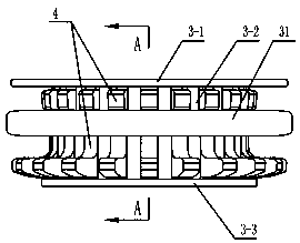
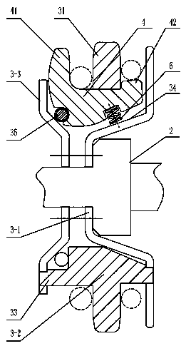
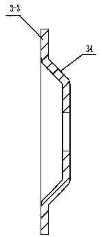
[0024] Such as figure 1 As shown, the present invention provides a self-locking rope winch, which includes a drive wheel body 3 that can rotate under the drive of the power device, and the drive wheel body 3 is connected with multiple rings that can swing and are distributed along the interval ring of the drive wheel body. A swing briquetting block 4, one end of the oscillating briquetting block 4 is provided with a pressing arm 41, the other end is provided with a driving part 42, and the driving wheel body 3 is provided with a radially outward extension and is located between the pressing arm and the driving part. The ring shoulder 31 of the pressing arm 41 and the ring shoulder 31 form a ring groove for the rope to pass through. Ring protruding shoulder 31, the return mechanism that drives the swing pressure block to return is housed on the driving wheel body 3, refer to figure 1 , that is to say, when an external force is applied to the driving part, when the driving part...


PUM


Abstract

The invention discloses a self-locking rope winch. The self-locking rope winch comprises a drive wheel body which can be driven by a power device to rotate, wherein a plurality of swing pressure blocks which can swing and are distributed along the drive wheel body in a ring-shaped mode in a spaced mode are connected on the drive wheel body; ends of the swing pressure blocks are equipped with pressing arms, and the other ends of the swing pressure blocks are equipped with drive parts; a ring convex shoulder which extends in a radial direction and is positioned between the pressing arms and thedrive parts is arranged on the drive wheel body; a ring slot for allowing a rope to pass through is formed between the pressing arms and the ring convex shoulder; and the drive parts act, so that theswing pressure blocks swing for enabling the pressing arms to extrude the rope to the ring convex shoulder; and a return mechanism for driving the swing pressure blocks to return is arranged on the drive wheel body. The self-locking rope winch can realize rope slip, can perform long-distance vertical lifting or transverse moving, and has the advantage effects of being high in safety performance, high in transporting efficiency and simple in structure.

Description

technical field [0001] The invention relates to a self-locking rope winch. Background technique [0002] At present, there are many load-carrying devices with lifting functions, such as cranes, hoisting machinery, cranes, lifting pulley blocks, etc. These lifting load-carrying devices need to be used in specific occasions, and sometimes due to environmental conditions, the existing lifting load-carrying devices cannot be used. . When it is necessary to move heavy objects over long distances, the above-mentioned lifting equipment is mostly used for transportation, and its labor efficiency is low. For example, it is necessary to transport heavy objects from the bottom of the mountain to the mountain, and tools such as cable cars need to be used. The labor cost is high and the efficiency is low. At present, there is no special tool that is simple and can carry out vertical transportation or translational transportation of heavy objects. [0003] The applicant has disclosed se...

Claims


Application Information

Patent Timeline
IPC IPC(8): B66D1/30
Inventor 赵修和赵睿熙郑明智
Owner WEIFANG WANREN ELECTROMECHANICAL TECH
Learn More