Exploration drill bit and manufacturing process thereof

A technology for exploring drill bits and probe holes. It is applied in the direction of manufacturing tools, drill bits, and drilling tools. It can solve problems such as breakage of push rods, failure of users to connect, and low built-in battery power to achieve the effect of fastening connections.

Active Publication Date: 2019-06-21
无锡锡钻地质装备有限公司
View PDF11 Cites 8 Cited by
  • Summary
  • Abstract
  • Description
  • Claims
  • Application Information

AI Technical Summary

Problems solved by technology

[0012] 1. The Bluetooth transmission distance is limited. When the drill bit is located in a deep underground position, the user cannot connect to the Bluetooth device on the drill bit through Bluetooth;
[0013] 2. The power of the built-in battery is too small to drive equipment such as hydraulic pumps;
[0014] 3. There is no reliable connection mechanism between the cone tip and the drill body, and the torque of the drill bit is extremely high. Only connecting the cone tip and the drill body with the push rod will cause the push rod to break when the drill bit is working;
[0015] 4. When the cone tip and the drill body are separated, dust will enter between the anti-seepage gasket and the cone tip, causing the cone tip and the drill body to fail to fit after reset;

Method used


Image

  • Exploration drill bit and manufacturing process thereof
  • Exploration drill bit and manufacturing process thereof
  • Exploration drill bit and manufacturing process thereof

Examples


Embodiment Construction

[0068] The technical solutions of the present invention will be further described below in conjunction with the accompanying drawings and through specific implementation methods.

[0069] Wherein, the accompanying drawings are only for illustrative purposes, showing only schematic diagrams, rather than physical drawings, and should not be construed as limitations on this patent; in order to better illustrate the embodiments of the present invention, some parts of the accompanying drawings will be omitted, Enlargement or reduction does not represent the size of the actual product; for those skilled in the art, it is understandable that certain known structures and their descriptions in the drawings may be omitted.

[0070] In the drawings of the embodiments of the present invention, the same or similar symbols correspond to the same or similar components; , "inner", "outer" and other indicated orientations or positional relationships are based on the orientations or positional ...


PUM


Abstract

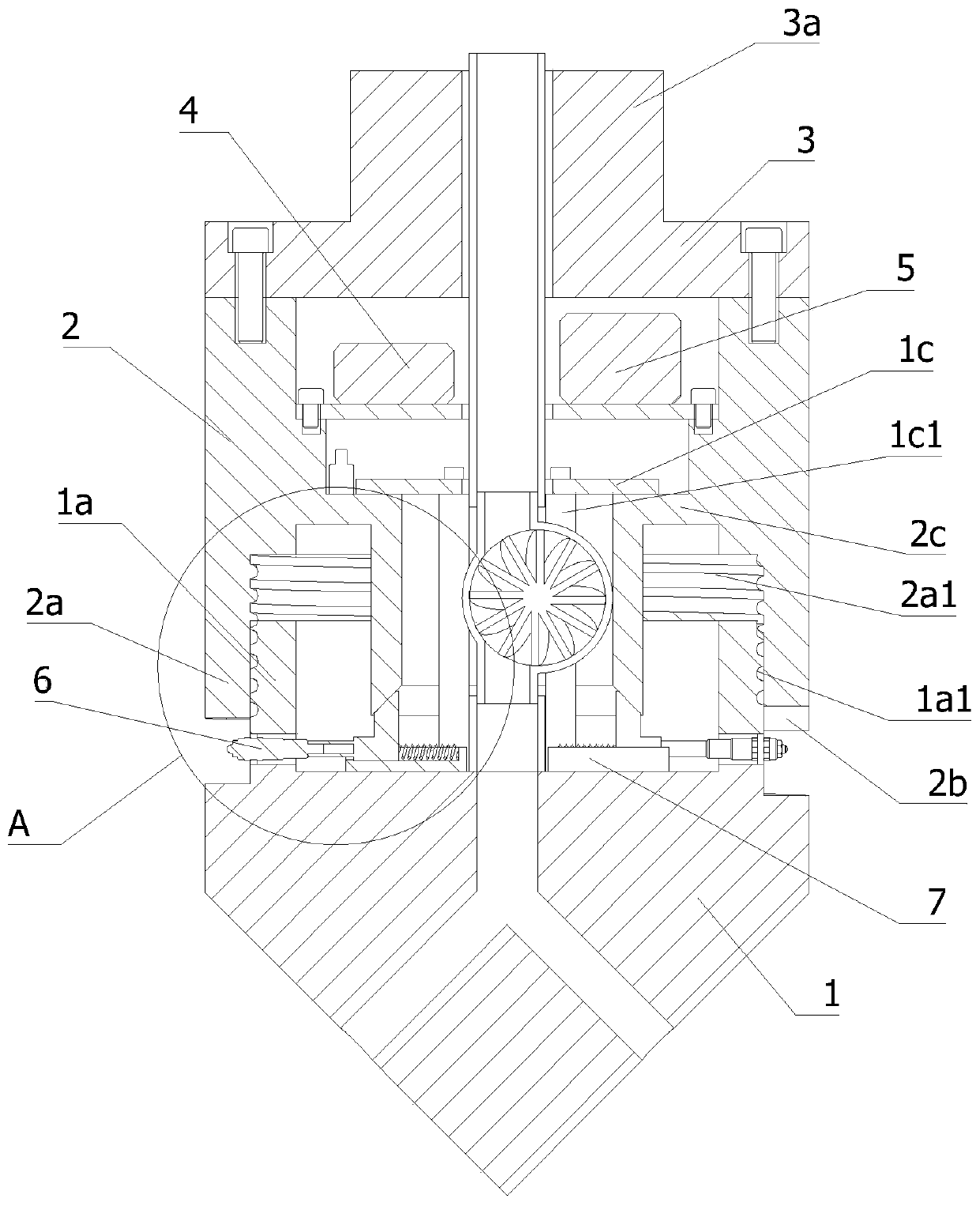
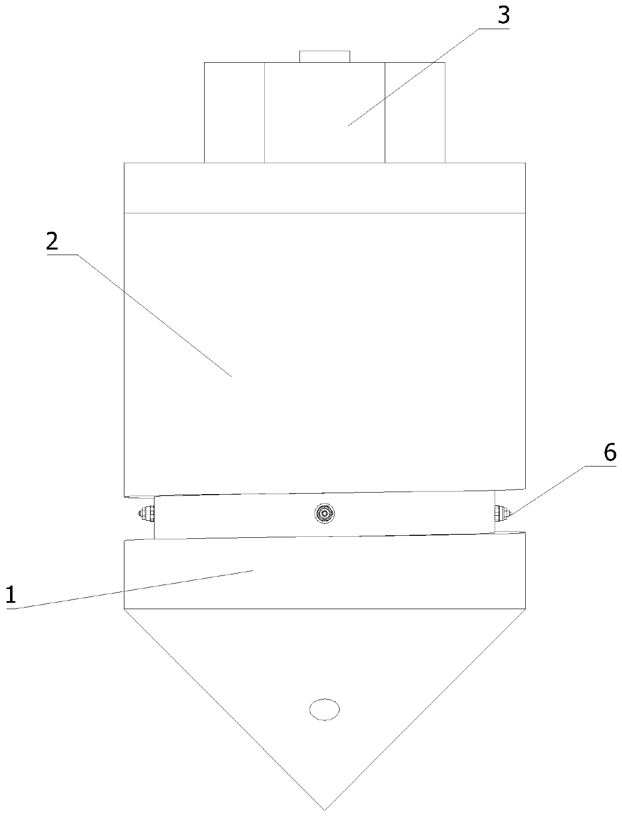
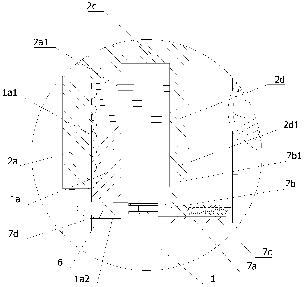
The invention relates to the field of geological exploration equipment, and particularly relates to an exploration drill bit and a manufacturing process thereof. The exploration drill bit comprises adrill tip, a drill body, a cover plate, a power supply, a controller and an infrared camera, wherein the drill tip, the drill body and the cover plate are sequentially connected from bottom to top, the drill tip is conical, the drill body is cylindrical, the cover plate is disc-shaped, a cavity is formed in the drill point, the drill body and the cover plate, the power supply, the controller and the infrared camera are mounted in the cavity, and the power supply and the infrared camera are electrically connected with the controller; an inner connecting ring vertically extending upwards is arranged at the top end of the drill tip, an outer connecting ring vertically extending downwards and arranged on the inner connecting ring in a sleeving mode is arranged at the bottom end of the drill body, the inner connecting ring is in threaded fit with the outer connecting ring, and a plurality of probe holes horizontally penetrating through the lower half portion of the inner connecting ring arefurther formed in the inner connecting ring. The drill tip and the drill body of the drill bit can be easily separated and folded, connection is firm after folding, the structure is reasonable, and sealing performance is good.

Description

technical field [0001] The invention relates to the field of geological exploration equipment, in particular to an exploration drill bit and a manufacturing process thereof. Background technique [0002] Drilling is an important technical means in geological exploration work. A drilling rig is used to drill down from the surface of the earth to form a cylindrical borehole in the formation to identify and divide the formation. Cores, ore samples, and soil samples can be obtained from different depths in the borehole for analysis and research, to determine the physical and mechanical properties and indicators of rock and soil layers, and to provide design needs. The drilling rigs used are mainly divided into two types: rotary type and impact type. [0003] Drilling is an investigation method that uses a shovel to take soil samples to observe underground remains. Its advantage is that it can directly go deep into the ground for sampling and observation, and can directly and ...

Claims


Application Information

Patent Timeline
Patent Type & Authority Applications(China)
IPC IPC(8): E21B10/00E21B10/62E21B10/60E21B47/002E21B12/06B23P21/00
Inventor 张世文徐颂贤
Owner 无锡锡钻地质装备有限公司
Why Eureka
Try Eureka