Heating supply system with heat energy storage devices for heating supply network user sides

A technology of thermal energy storage and heating system, applied in heating system, hot water central heating system, household heating, etc., can solve the problems of high idle rate, low utilization rate of thermal pipe network, and high heating cost, etc. achieve the effect of increasing compatibility

Pending Publication Date: 2019-06-21
SHENYANG SHIJIE ELECTRIC
View PDF0 Cites 1 Cited by
  • Summary
  • Abstract
  • Description
  • Claims
  • Application Information

AI Technical Summary

Problems solved by technology

Since the large heat source station shared by multiple users needs to supply heat to users with different temperatures, different pressures and thermal stability requirements higher than the output stability of the general thermal pipe network, it is necessary to lay multiple heat pipe network loops, such as: heat for heating users The pipe network is idle in the non-heating season, and the heat pipe network of industrial users changes with the production demand and has nothing to do with the season; the output capacity of the heat pipe network laid by the large heat source station is limited by the upper limit, and the heat demand of the users connected to the heat pipe networ

Method used


Image

  • Heating supply system with heat energy storage devices for heating supply network user sides
  • Heating supply system with heat energy storage devices for heating supply network user sides

Examples


Embodiment

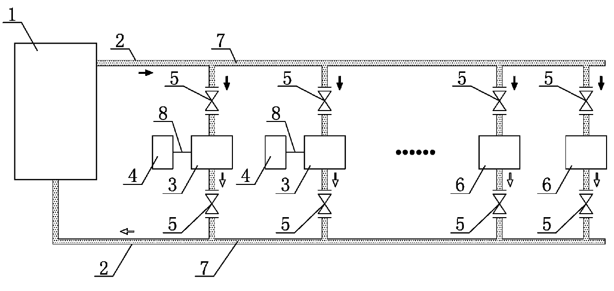
[0017] Depend on figure 1 As shown in the figure, 1 in the figure shows that the large heat source station is the waste heat heating unit of the thermal power plant, 2 shows that the heat pipe network is a circulation pipeline for transmitting superheated steam at a temperature of 280°C and a pressure of 1.6MPa in the thermal power plant, and the solid energy storage body 3 is solidified on two diameter DN50, pouring material with 20G seamless metal pipe outer thickness of 150mm, the 20G seamless metal pipe is connected to the heat pipe network 2, and forms a loop with the heat pipe network 2, while another 20G seamless metal pipe is connected to the The regenerative user 4 is connected to the regenerative user 4 to form a circuit; the heat source required by the regenerative user 4 is 140°C saturated steam, 5 is a valve group, and the heat source required by the 6 direct supply user is 60°C-80 ℃ hot water, 7 heat transfer medium is superheated steam, 8 is the regenerative use...


PUM


Abstract

The invention discloses a heating supply system with heat energy storage devices for heating supply network user sides. The heating supply system comprises a large heat source station, heating supplypipe networks, heat transfer media, valve sets and direct-supply type users. The heating supply system is characterized in that solid energy storage bodies with insulating layers arranged outside arefurther connected into the same heating supply pipe networks led out of the large heat source station and connected into the direct-supply type users; metallic pipelines communicating with the heatingsupply pipe networks are further distributed inside the solid energy storage bodies, and heat accumulating type user pipe networks with the output ends communicating with heat accumulating type userinput ends are further arranged inside the solid energy storage bodies; and the heating supply pipe networks of the large heat source station, the solid energy storage bodies communicating with heat accumulating type users and the direct-supply type users form a heat release loop through the valve sets. The heating supply system has the positive effects that the connected-in solid energy storage bodies are used for improving the compatibility and transmitting capacity of heating supply networks and increasing the utilization rate of pipe networks on the same heating supply pipe networks, and users not matched with the temperature, pressure and heating supply stability indexes of the heating supply pipe networks can obtain heating supply services of the large heat source station.

Description

technical field [0001] The invention relates to the technical field of heat supply, in particular to a heat supply system with a thermal energy storage device at the user end of the heat network arranged between the heat pipe network and the heat user, so as to realize the connection of different temperatures and pressures in the same heat cycle pipe network. Capabilities required by users. Background technique [0002] In recent years, domestic provinces have generally used heat extracted by thermal power plants with an installed capacity of more than 300,000 kilowatts or replaced small coal-fired heat source stations with large heat source stations with a heating capacity of more than 100 steam tons to provide heat for users. The environment has a remarkable effect in reducing air pollution. Since the large heat source station shared by multiple users needs to supply heat to users with different temperatures, different pressures and thermal stability requirements higher t...

Claims


Application Information

Patent Timeline
IPC IPC(8): F24D11/00F24D3/10
CPCY02A30/60
Inventor 朱建新崔英俊
Owner SHENYANG SHIJIE ELECTRIC
Why Eureka
Try Eureka