A light source modulation method for confocal scanning microscope

A technology of light source modulation and microscopy, which is applied in the field of confocal scanning optical imaging instruments, can solve the problem of insufficient image quality, and achieve the effect of minimizing the amount of light radiation of the sample

Active Publication Date: 2020-04-03
BRIGHTVIEW MEDICAL TECH NANJING CO LTD
View PDF6 Cites 0 Cited by
  • Summary
  • Abstract
  • Description
  • Claims
  • Application Information

AI Technical Summary

Problems solved by technology

The result of this problem is that in order to get a good enough sample image signal, the sides of the sample must receive 7 times more light dose than the middle of the sample
If only 1 / 7 of the dose is used to ensure that the images on both sides of the sample have a good enough signal-to-noise ratio, then the middle of the sample must be underexposed and the image quality cannot meet the specified requirements.

Method used


Image

  • A light source modulation method for confocal scanning microscope
  • A light source modulation method for confocal scanning microscope
  • A light source modulation method for confocal scanning microscope

Examples


Embodiment 1

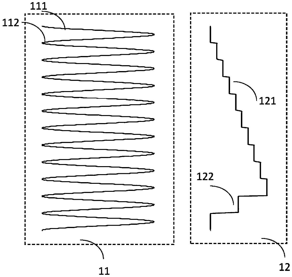
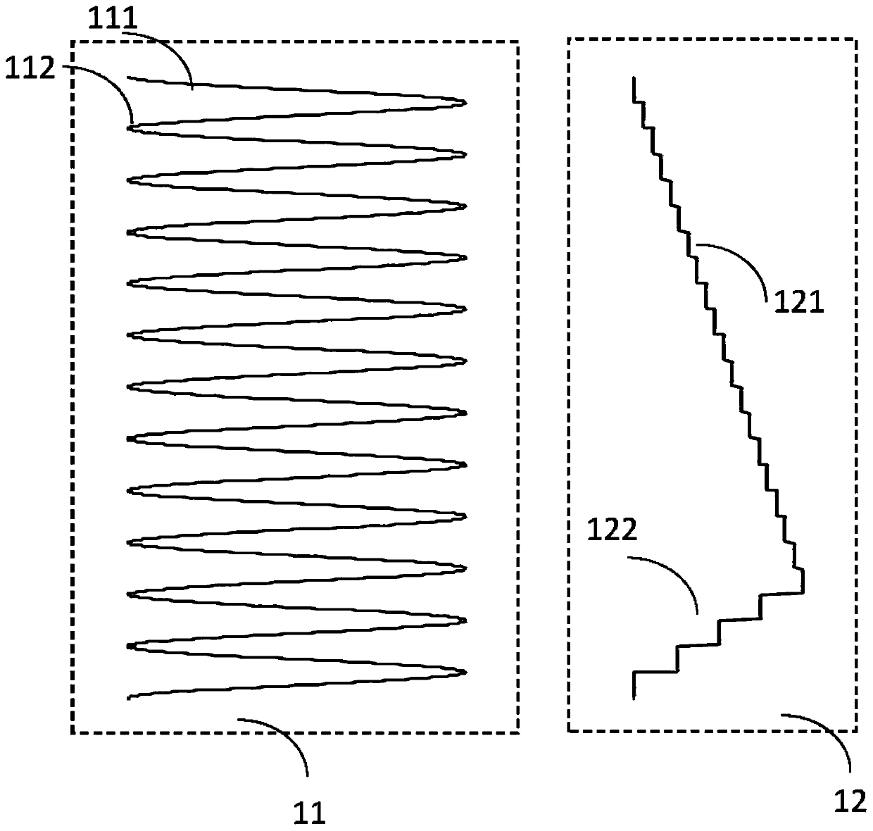
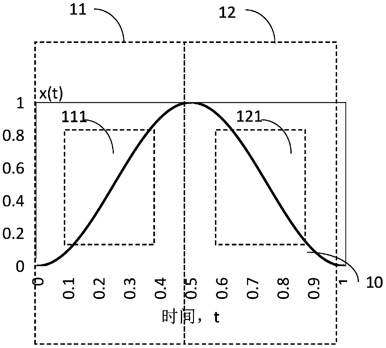
[0070] refer to Figure 2A In the image window 111 and the image window 121, a relatively linear part is taken between the fast resonant mirror scanning window 11 and the slow linear scanning mirror scanning window 12. Since the sample image is severely stretched and distorted on both sides of the sample with a low speed resonant mirror, will cause the image not to apply.

[0071] In the above-mentioned embodiment 1, when a super luminescent diode (SLD, Super Luminescent Diode) is used as the imaging light source, this method is relatively easy to implement. A typical SLD usually has an opto-isolator with a built-in bandwidth of 100kHz to 200kHz, while the resonant frequency of a common fast resonant mirror is generally between 4kHz and 16kHz. Therefore, the SLD has a bandwidth of 100 kHz to 200 kHz, which is fast enough to reflect the switching frequency from the fast resonant mirror. According to the Nyquist sampling theory, it can be guaranteed that no sampling distortion ...

Embodiment 2

[0079] The method adopted in this embodiment is to use a light source power modulator, and a typical application is to use an Acousto-Opto Modulator (AOM, Acousto-Opto Modulator) to modulate the light source. The modulation method starts from formula (5). In the formula (5), if the transmitting end power P of the light source 0 After AOM, and then perform nonlinear modulation on AOM, get:

[0080]

[0081] Among them, k is the attenuation coefficient of the AOM, which is a constant. Substitute formula (6) into formula (5) to obtain the radiation distribution of the light source in the sample space:

[0082] I'(x)=ΔI(x) / Δx=k·P 0 / ω (7)

[0083] Among them: ΔI(x) is the amount of radiation received per unit space size of the scanned sample, x is the scanning space position; Δx is the position change; ω is the angular velocity of the fast resonant mirror.

[0084] That is to say, after the power modulation of the formula (6), the radiation distribution of the light source...

Embodiment 3

[0095] The method adopted in this embodiment is to combine the methods of Embodiment 1 and Embodiment 2 at the same time, and at the same time turn off the SLD light source outside the image window, and then superimpose a power modulator, such as an AOM, to perform power modulation on the output end of the light source.

[0096] like Figure 6A As shown, simultaneous power modulation 211, 221 and light source switch modulation 311, 321 are performed on the light source in the forward scanning image window 111 and reverse scanning image window 121 of the fast resonant mirror through the AOM.

[0097] like Figure 6B As shown, simultaneous power modulation 211 and light source switch modulation 311 are performed on the light source in the forward scanning image window 111 of the fast resonant mirror through the AOM.

[0098] like Figure 6C As shown, the light source is subjected to simultaneous power modulation 221 and light source switch modulation 321 through the AOM in the...


PUM


Abstract

The invention discloses a confocal scanning microscope light source modulation method, which comprises the following steps of: modulating a light source by adopting a light source power modulator, andcarrying out nonlinear modulation on the transmitting end power of the light source through the light source power modulator; performing simultaneous power modulation on a forward scanning sampling window and a reverse scanning sampling window of the light source output end on the fast resonant mirror; or performing power modulation on the light source output end in the forward scanning samplingwindow; or performing power modulation on the light source output end in the reverse scanning sampling window. By adopting the method and the device, the purpose of minimizing the light radiation quantity on the surface of the sample can be achieved.

Description

technical field [0001] The present invention relates to confocal scanning optical imaging instrument technology, in particular to a confocal scanning microscope light source modulation method, which can be used for two-dimensional scanning of biological samples (such as skin, fundus and other biological tissues, which can be referred to as "sample" for short) , to obtain high-definition two-dimensional images of biological samples. Background technique [0002] Confocal scanning microscopy optical systems, usually using a fast resonant scanning mirror and a slow linear scanning mirror in the orthogonal direction, perform two-dimensional scanning of the sample to acquire a two-dimensional image of the sample. [0003] Figure 1A shows how a typical scanning mirror works. like Figure 1A As shown, the fast resonant mirror scanning window 11 continuously scans the sample in the first direction in a sinusoidal manner, wherein any sinusoidal scanning period can be decomposed int...

Claims


Application Information

Patent Timeline
Patent Type & Authority Patents(China)
IPC IPC(8): G02B21/00G02B21/06
Inventor 张金莲张杰
Owner BRIGHTVIEW MEDICAL TECH NANJING CO LTD
Why Eureka
Try Eureka