Automatic assembly machine for scissor foot

An automatic assembly machine and scissor foot technology, which is applied in the direction of electrical components, electric switches, circuits, etc., can solve the problems of being unable to adapt to internal and external shear assembly, difficult to design manipulators, and difficult to install internal shears, etc., to achieve good assembly effect and executive mechanism The effect of efficient, fast and reliable assembly

Pending Publication Date: 2019-06-21
重庆半步自动化设备有限公司
View PDF0 Cites 14 Cited by
  • Summary
  • Abstract
  • Description
  • Claims
  • Application Information

AI Technical Summary

Problems solved by technology

The scissor foot is a very small and thin plastic plate-shaped part, and its size is much smaller than the common notebook keyboard keys. Therefore, in actual assembly, it is difficult to grasp the inner scissors well. Not only is it easy to deform the frame-shaped internal shear, but it is also difficult to design such a small-sized manipulator.
In addition, the current automatic assembly machines for scissor feet are all designed for the corresponding part forms of internal shears and external shears. Most of the current scissor foot parts are formed by arranging internal shears and external shears on both sides of a rod-shaped material head. form, that is, the left side is full of internal shears, and the right side is all external shears, and those skilled in the art have designed a new forming layout structure of scissors foot parts, that is, an accessory unit, namely Figure 4 As shown, both sides of the material head are set up as a group of inner shears and outer shears on the same side, that is, the inner shears and outer shears form a group adjacent to each other from the left side to the bottom, and the inner shears and outer shears form a group downwards. group, and so on, and the right side is the same. Therefore, for the assembly equipment of this new type of accessory unit, it is necessary to adjust its structural layout of shearing, assembly, and stripping, and the current equipment cannot adapt to this form of internal and external shearing. assembly, especially it is difficult to quickly and accurately install the inner shears in the outer shears

Method used


Image

  • Automatic assembly machine for scissor foot
  • Automatic assembly machine for scissor foot
  • Automatic assembly machine for scissor foot

Examples


Embodiment Construction

[0024] The implementation of the present invention will be described by specific specific examples below, and those skilled in the art can easily understand other advantages and effects of the present invention from the content disclosed in this specification.

[0025] Below in conjunction with accompanying drawing and embodiment the present invention will be further described:

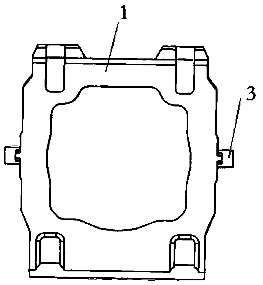
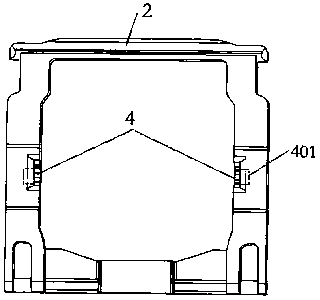
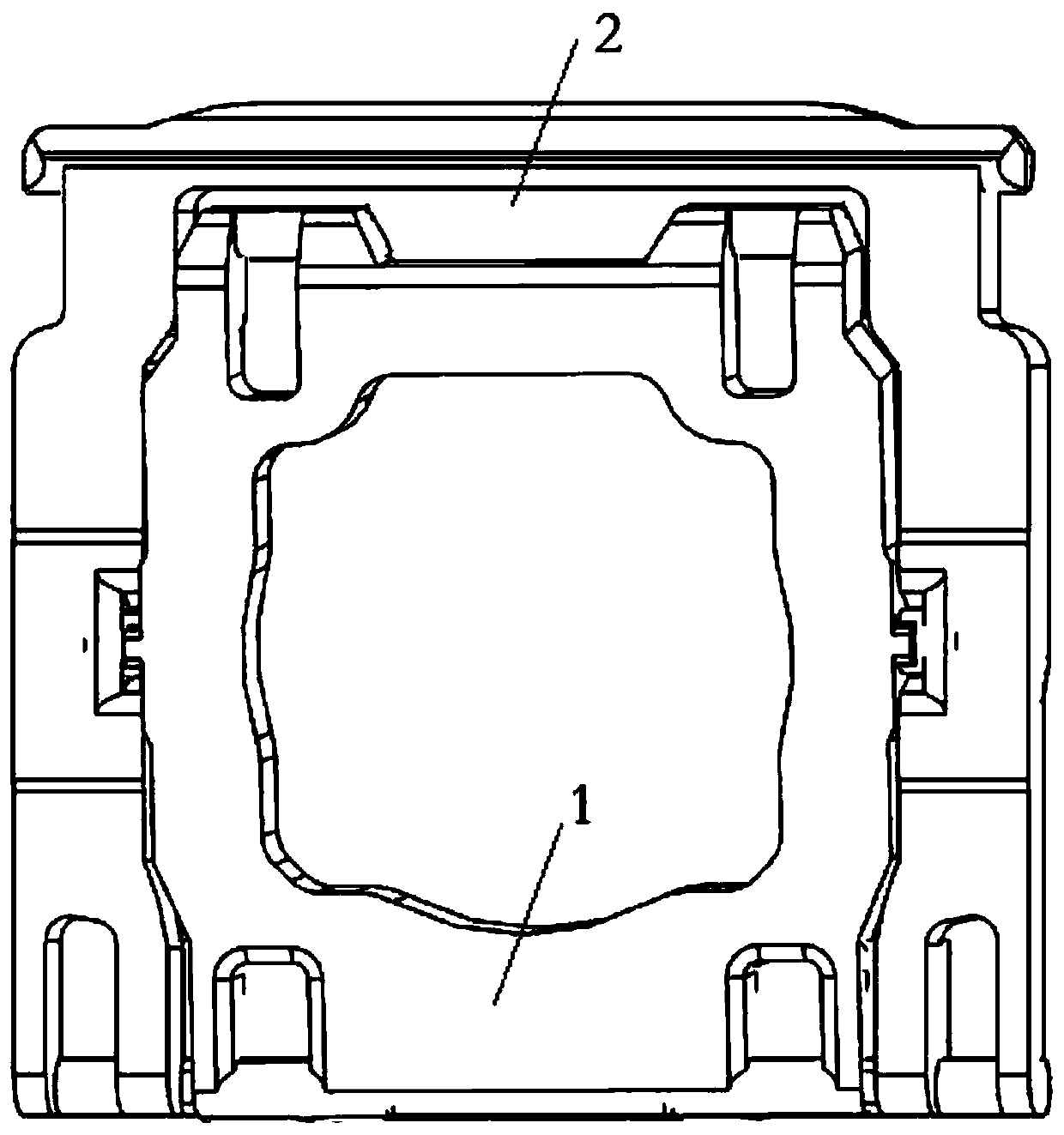
[0026] Such as Figure 5 Shown, a kind of scissor foot automatic assembly machine, it mainly comprises the lower die 200 that can move horizontally, the upper die 100 that can move horizontally and vertically, the material cutting mechanism 300 that moves vertically, the material stripping mechanism 400; Wherein, the lower mold 200 is used to place the inner shears and outer shears in advance and the upper mold 100 grabs the inner shears from the lower mold 200 to start assembly, and the cutting mechanism 300 is engaged with the lower mold 200 to make the inner shears The shears and outer shears are ...


PUM


Abstract

The invention discloses an automatic assembly machine for a scissor foot and belongs to the technical field of scissor-foot assembly. The automatic assembly machine comprises a lower mold capable of horizontal movement, an upper mold capable of both horizontal and vertical movements, a vertically moving cutting mechanism and a stripping mechanism, wherein the lower mold is configured to pre-placeinner and outer shears, the upper mold grasps the inner shear from the lower mold to start assembly, the cutting mechanism is engaged with the lower mold to separate the inner and outer shears from the head material, the groove bottom of an inclined base groove on the lower mole has a thimble protruding toward the open end thereof, the outer shear is placed obliquely through the groove bottom, thelower side of the outer portion of the outer shear is in sliding contact with the top surface of the thimble when the front rotating shaft of the inner shear continues to translate forward after being clamped into the front axle hole of the outer shear such that the rear side of the outer shear is gradually lifted upward to finally enable embedded matching of the rear axle hole of the outer shearand the rear rotating shaft of the inner shear. The automatic assembly machine has a reasonable structure, continuous processes, strong pertinence and high assembly effect and efficiency.

Description

technical field [0001] The invention belongs to the technical field of notebook keyboards, in particular to a scissor foot automatic assembly equipment for notebook keyboards. Background technique [0002] Scissor legs are an essential component of a laptop keyboard, and its structure is shown in image 3 shown; among them, such as figure 1 As shown, a cylindrical rotating shaft 3 (front rotating shaft, rear rotating shaft) is all arranged on the front and rear both sides outer walls of its inner shear 1, as figure 2 As shown, two shaft holes 4 (front shaft hole and rear shaft hole) that are snap-engaged with the front shaft and the rear shaft are respectively arranged on the front and rear inner side walls of the outer scissors 2, and the free end of the shaft has a shaft hole toward the side of the shaft hole. A wedging surface that has been shaved off, the specific shape of the shaft hole 4 is a groove with an arc-shaped cross section coaxially connected with a circula...

Claims


Application Information

Patent Timeline
Patent Type & Authority Applications(China)
IPC IPC(8): H01H13/88H01H11/00
Inventor 向小木任小敏李宏波
Owner 重庆半步自动化设备有限公司
Why Eureka
Try Eureka