Computer power line connector

A computer power supply and wire connector technology, applied in the computer field, can solve problems such as poor matching, and achieve the effects of improving safety, enhancing firmness, and facilitating plugging and unplugging

Active Publication Date: 2019-06-21
FEIDA TECH CO LTD
View PDF5 Cites 8 Cited by
  • Summary
  • Abstract
  • Description
  • Claims
  • Application Information

AI Technical Summary

Problems solved by technology

[0005] The purpose of the present invention is to provide a computer power cord connector that is easy to plug in and not easy to fall off in order to solve the problem of poor matching between the computer power cord connector and the computer jack

Method used


Image

  • Computer power line connector
  • Computer power line connector
  • Computer power line connector

Examples


Embodiment 1

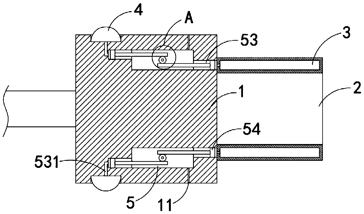
[0028] Such as Figure 1-3 As shown, a computer power cord connector includes a grip portion 1 and a plug portion 2. The plug portion 2 is fixedly connected to the front side wall of the grip portion 1, and the plug portion 2 is electrically connected to the computer power cord. A ring-shaped airbag 3 is fixedly sleeved, and a pressing ring 4 is fixedly sleeved outside the holding portion 1. The ring-shaped airbag 3 and the pressing ring 4 are made of elastic materials such as rubber. The holding portion 1 is provided with a cavity 5, 5 includes:

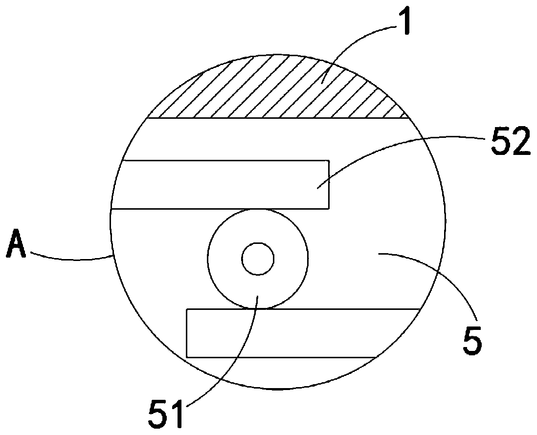
[0029] Gear 51, the gear 51 is rotatably connected with the side wall of the cavity 5 through a rotating shaft, the gear 51 is fixedly connected with the rotating shaft coaxially, and both ends of the rotating shaft are rotatably connected with the side walls on both sides of the cavity 5;

[0030] Two racks 52, the two racks 52 are respectively located on both sides of the gear 51 and symmetrically arranged about the center of the gear...

Embodiment 2

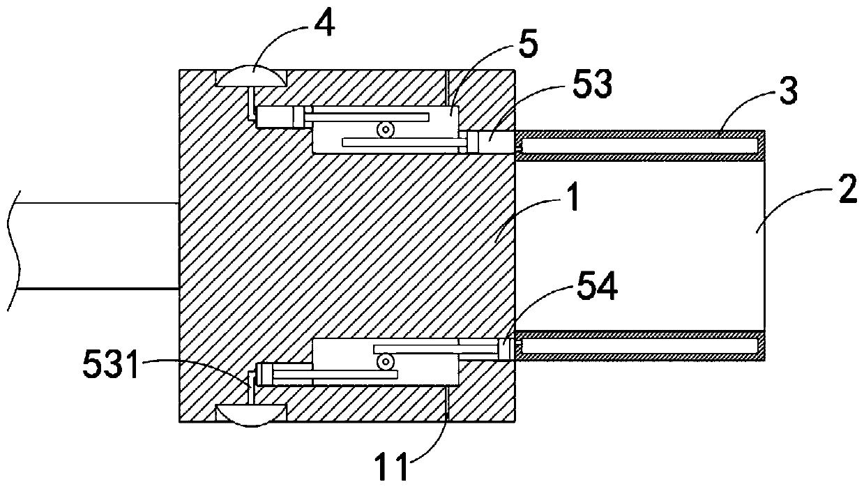
[0037] Such as Figure 4 As shown, the difference between this embodiment and Embodiment 1 is that the pressing ring 4 is composed of a plurality of elastic rings 41 distributed equidistantly, and the plurality of elastic rings 41 communicate with the channel 53 through the air guide holes 531 arranged in a tree shape.

[0038] In this embodiment, by arranging multiple elastic rings 41, not only can the coverage area of ​​the pressing ring 4 be increased, and the difficulty of use for the operator is reduced, and the evenly distributed elastic rings 41 can play a better anti-slip effect, and further improve the operation. Safety in the process.

Embodiment 3

[0040] Such as Figure 5 As shown, the difference between this embodiment and the second embodiment is that an annular suction cup 6 is embedded on the front end side wall of the holding portion 1, and the end of the stabilizing hole 11 away from the cavity 5 is communicated with the annular suction cup 6.

[0041] In this embodiment, when the elastic ring 41 is pressed, the gas in the cavity 5 will be discharged to the outside along the pressure stabilizing hole 11. When the elastic ring 41 is loosened, the suction cup 6 is adsorbed on the computer socket and is empty. The cavity 5 has a larger volume and a smaller internal air pressure. Under the action of the external atmospheric pressure, the power cord plug will be tightly attached to the computer socket, which can further enhance the firmness of the connection between the power cord and the computer.


PUM


Abstract

The invention belongs to the field of computers, and particularly relates to a computer power line connector. The computer power line connector comprises a holding part and a plug part, wherein the plug part is fixedly connected to the side wall of the front end of the holding part, and is characterized in that an annular air bag is fixedly arranged outside the plug part in a sleeving mode; a pressing ring is fixedly sleeved outside the holding part; a cavity is formed in the holding part; a gear, two racks and two channels are arranged in the cavity, wherein the gear is rotationally connectedwith the side wall of the cavity through a rotating shaft; the two racks are positioned on two sides of the gear and are symmetrically arranged relative to the center of the circle of the gear, and the two racks are meshed with the gear; the two channels are arranged in the side walls of the two sides of the cavity respectively, and the channels correspond to the positions of the racks; and one channel is communicated with the pressing ring through an air guide hole, and the other channel is communicated with the annular air bag. According to the connector, the matching degree between the power line connector and the computer jacks can be greatly improved, the effects of easy plugging and firm connection can be realized, and the stability of a computer in the using process can be improved.

Description

Technical field [0001] The invention belongs to the field of computers, and particularly relates to a computer power cord connector. Background technique [0002] The computer is one of the most advanced scientific and technological inventions in the 20th century. It has had an extremely important impact on human production and social activities and has become an indispensable tool in the information society. [0003] The computer needs to be connected to an external power supply through a special power cord during use. The existing power cord connector is generally made of hard rubber material. Due to factors such as craftsmanship, material, and quality, the power cord connector is connected to the power jack of the computer. The matching degree is poor. When the gap between the two is too small, it will be difficult to plug and plug, which brings great inconvenience to the maintenance of the computer. When the gap between the two is too large, it is easy to loosen And, because t...

Claims


Application Information

Patent Timeline
IPC IPC(8): H01R13/629H01R13/639H01R24/28
Inventor 刘改
Owner FEIDA TECH CO LTD
Why Eureka
Try Eureka