Distributed energy consumption device and module fault bypass control method

An energy-consuming device, distributed technology, applied in circuit devices, emergency protection circuit devices, output power conversion devices, etc., can solve the problems of low reliability, overvoltage burnout of power devices, and diode overvoltage breakdown, etc. Simplify the control strategy, facilitate the overall design, and reduce the effect of current impact

Active Publication Date: 2019-06-21
NR ENG CO LTD +1
View PDF10 Cites 6 Cited by
  • Summary
  • Abstract
  • Description
  • Claims
  • Application Information

AI Technical Summary

Problems solved by technology

[0003] In the prior art, power semiconductor devices are often used to form switch strings. For example, IGBTs are directly connected in series and concentrated resistance schemes are used. The IGBT strings withstand high voltage, and the concentrated resistance consumes energy. The consistency requirements of switching off and off are extremely high. Once there is an inconsistency, it will cause overvoltage and burnout of the power device. Since it will be turned on and off continuously during operation, the risk of device damage is high.
Patent CN102132484B-converter with distributed braking resistors proposes a modular solution, but this solution uses a large number of power devices, including 4 groups of power semiconductor devices, and the reliability of power semiconductor devices is relatively low, making the entire module The failure rate is higher, and there are disadvantages of high cost and low reliability
Secondly, in this scheme, the potential of the bridge arm formed by the diode is complex, and the upper tube of the diode bridge arm is connected to the adjacent module, and the capacitor cannot clamp it. When the device is running, due to the complicated operation mode, it is difficult to work between modules. When not synchronized, the potential between the modules is uncertain, and the diode is at risk of overvoltage breakdown
In addition, this solution integrates two bridge arms composed of power semiconductor devices in one module, and there is a potential connection between the bridge arms, which increases the difficulty of structural design

Method used


Image

  • Distributed energy consumption device and module fault bypass control method
  • Distributed energy consumption device and module fault bypass control method
  • Distributed energy consumption device and module fault bypass control method

Examples


Embodiment Construction

[0024] In order to make the purpose, technical solutions and advantages of the embodiments of the present application more clear, the specific implementation manners of the technical solutions of the present application will be described in more detail and clearly below in conjunction with the drawings and embodiments. However, the specific embodiments and examples described below are for the purpose of illustration only, rather than limiting the application. It only includes a part of the embodiments of the present application, but not all of the embodiments. Other embodiments obtained by those skilled in the art through various changes of the present application all belong to the scope of protection of the present application.

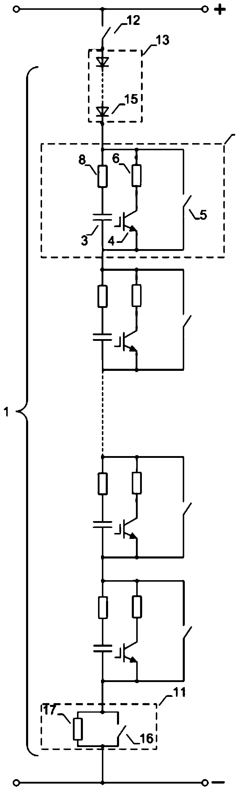
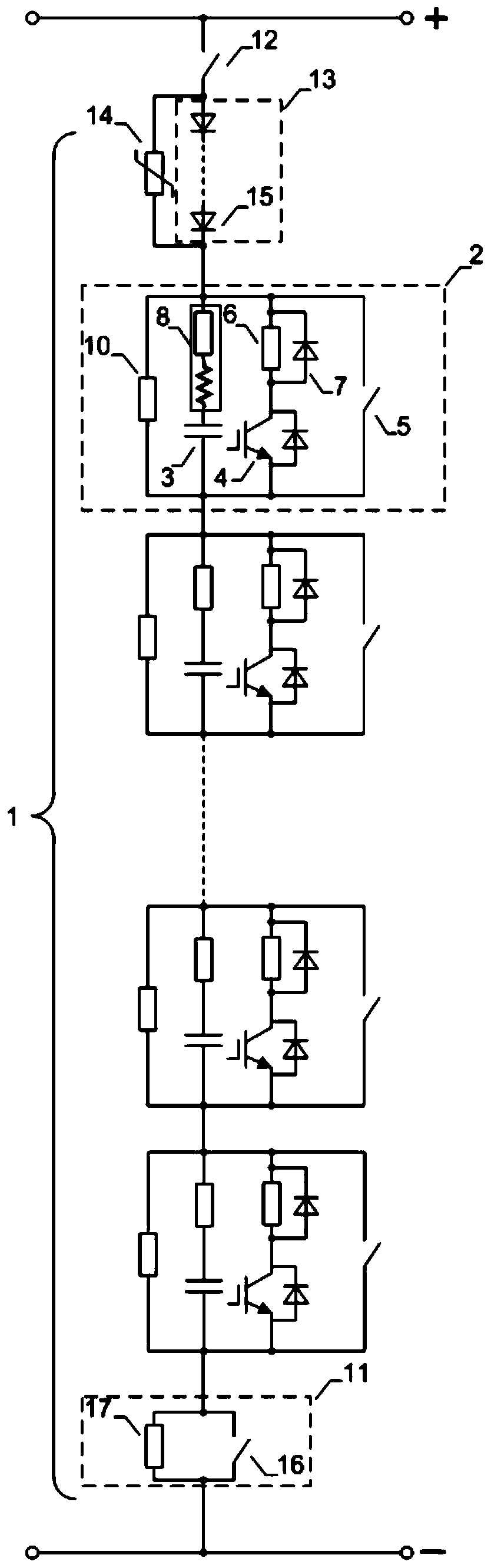
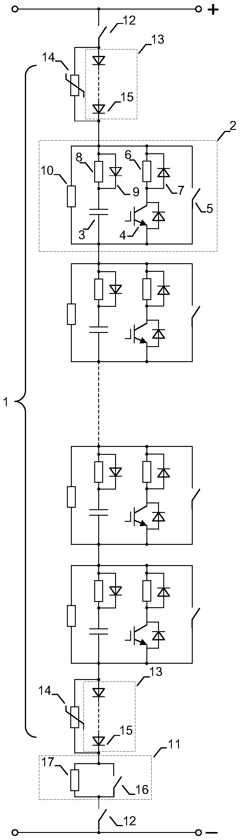
[0025] figure 1 It is a schematic composition diagram of a distributed energy consumption device provided by an embodiment of the present application. Such as figure 1 As shown, the distributed energy consumption device 1 includes at least two volt...


PUM


Abstract

The invention provides a distributed energy consumption device and a module fault bypass control method. The device comprises at least two voltage-sharing energy dissipation modules, at least one one-way conduction module, at least one charging module and at least one isolation switch, wherein each voltage-sharing energy dissipation module comprises an energy storage unit, an energy consumption unit and a bypass switch which are connected in parallel; the energy storage unit comprises an energy storage capacitor and a current limiter which are connected in series; the energy dissipation unit comprises an energy dissipation resistor and a first power semiconductor device which are connected in series; the at least one one-way conduction module comprises at least one second power semiconductor device; the at least one charging module comprises at least one resistor and at least one switch which are connected in parallel; and the at least one isolation switch is connected with the voltage-sharing energy dissipation modules, the one-way conduction module and the charging module in the same direction in series. According to the modular design scheme, the voltage sharing problem of the power device is solved, and the control strategy is simplified; the design scheme that the energy storage capacitor is connected with the current limiter in series to limit the current of the bypass switch is adopted, so that the current impact of the bypass switching on is reduced, and the reliability of the fault bypass is improved.

Description

technical field [0001] The application relates to the technical field of energy-saving optimization control of central air-conditioning system high-voltage direct current transmission technology, in particular to a distributed energy-consuming device and a module fault bypass control method. Background technique [0002] In the application field of HVDC transmission, especially in the application scenario of island power supply, when the receiving end fails, due to the power imbalance between the generating end and the receiving end, the DC line side quickly accumulates energy. If the energy is not consumed in time, it will As a result, the voltage of the DC line rises sharply, which seriously endangers the safety of equipment and the operation of the system. Therefore, the DC line energy consumption device plays a vital role in the DC transmission system. [0003] In the prior art, power semiconductor devices are often used to form switch strings. For example, IGBTs are di...

Claims


Application Information

Patent Timeline
Patent Type & Authority Applications(China)
IPC IPC(8): H02J3/36
CPCH02H9/04H02M1/32H02M1/34H02H9/042H02M1/36Y02E60/60H02H7/205
Inventor 汪涛陈武虞晓阳詹长江文继锋曹冬明谢晔源
Owner NR ENG CO LTD
Why Eureka
Try Eureka