
Rotor position detecting method of switched reluctance motor based on conducting phase flux linkage

A switch reluctance motor, rotor position detection technology, applied in the control of generator, motor generator control, AC motor control and other directions, can solve the problem of large controller memory space, complex interpolation calculation, position detection accuracy depends on the fineness of the three-dimensional table and other problems, to achieve the effect of simplifying the algorithm and calculation amount, and overcoming the complex structure

Inactive Publication Date: 2019-06-21
HARBIN UNIV OF SCI & TECH
View PDF8 Cites 0 Cited by
  • Summary
  • Abstract
  • Description
  • Claims
  • Application Information

AI Technical Summary

Problems solved by technology

The traditional flux linkage detection method needs to establish multiple three-dimensional data tables of rotor position angles, and the continuous real-time position of the rotor can be obtained through table look-up interpolation calculations, but the process of establishing three-dimensional data tables is time-consuming, interpolation calculations are complicated, and the position detection accuracy depends on The fineness of the table, and occupy a large memory space of the controller

Method used


Image

  • Rotor position detecting method of switched reluctance motor based on conducting phase flux linkage
  • Rotor position detecting method of switched reluctance motor based on conducting phase flux linkage
  • Rotor position detecting method of switched reluctance motor based on conducting phase flux linkage

Examples


Embodiment Construction

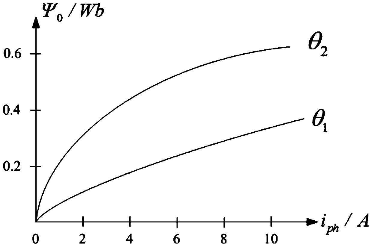
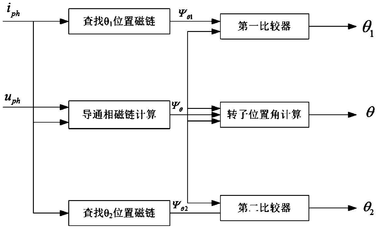
[0032] figure 1 It shows a rotor position detection method of a switched reluctance motor based on conducting phase flux linkage according to an embodiment of the present invention, taking a three-phase 12 / 8-pole switched reluctance motor as an example to carry out the present invention illustrate.

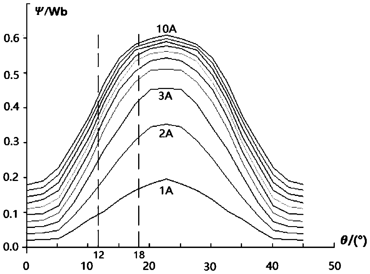
[0033] The number of poles of the switched reluctance motor rotor is N r =8, according to the working principle of the three-phase 12 / 8 switched reluctance motor, the turn-off angle of the current conduction phase and the turn-on angle of the next turn-on phase are both around 15°, in order to optimize the turn-on angle and turn-off angle For control, a switching commutation area needs to be planned, and the range of the commutation area is generally within 15°±3°.

[0034] In this example, the boundary angles of the switch commutation area are selected as θ 1 = 12° and θ 2 =18°, such as image 3 shown. image 3 The Ψ-θ curve obtained by fitting the measured data of the flux...


PUM


Abstract

The invention relates to a rotor position detecting method for a switched reluctance motor, and belongs to the technical field of rotor position detection of switched reluctance motors, in particularto a rotor position detecting method of a switched reluctance motor based on a conducting phase flux linkage. The method comprises the following steps of establishing a switch commutating rotor position interval bounded by the two flux linkage curves based on flux linkage curves corresponding to two rotor reference position angles; obtaining two reference position flux linkage curves by off-line testing, establishing two two-dimensional data tables, and obtaining two reference position flux linkages by calculating conducting phase real-time flux linkages and checking the two-dimensional data tables; comparing the conducting phase flux linkages with the two reference position flux linkages, and calculating to obtain a continuous rotor position angle. The rotor position detecting method realizes the continuous detection of the rotor position angle in the switching phase change region, omits unnecessary calculation and detection of the rotor position angle in the non-commutation region, simplifies the rotor position detection algorithm, and can conveniently realize the operational control of the non-position sensor of the switched reluctance motor.

Description

technical field [0001] The invention relates to a rotor position detection method of a switched reluctance motor, which belongs to the technical field of rotor position detection of a switched reluctance motor, in particular to a rotor position detection method of a switched reluctance motor based on a conduction phase flux linkage. Background technique [0002] With the development of the industrial age, switched reluctance motors have gradually entered the public's field of vision due to their excellent performance. Since the switched reluctance motor is a position closed-loop self-synchronous motor, it needs to obtain rotor information through a position sensor to operate normally. The position sensor is used in the switched reluctance motor to detect the commutation position of the rotor and provide commutation information for the motor driver. However, the existence of the position sensor increases the complexity of the switched reluctance motor structure, affects the ...

Claims


Application Information

Patent Timeline
Patent Type & Authority Applications(China)
IPC IPC(8): H02P21/18H02P25/089
Inventor 周永勤胡冠球王航王宁
Owner HARBIN UNIV OF SCI & TECH
Learn More