
Driving cabin assembly

A cockpit and assembly technology, applied in aircraft parts, aircraft accessories, transportation and packaging, etc., can solve the problems of drivers taking emergency equipment out of danger, affecting the cleanliness of the cabin, and not being able to be placed well. The effect of simple structure, convenient disposal of waste and convenient operation

Inactive Publication Date: 2019-06-25
张振扬
View PDF0 Cites 0 Cited by
  • Summary
  • Abstract
  • Description
  • Claims
  • Application Information

AI Technical Summary

Problems solved by technology

[0002] The cockpit assembly is an internal assembly of the cockpit that the pilot controls the aircraft. It is installed quickly and is easy to disassemble and replace. The cockpit is the head of the aircraft and is the center of order and control in the aircraft. The occupant feels comfortable to operate, and contains all the advanced navigation and various control systems used for air travel, just as important as other components that provide all the necessities of the occupant, it has been widely used, when in use due to internal There are many things, and the emergency equipment cannot be found in an emergency, which affects the driver to take the emergency equipment to get out of danger; the existing cockpit assembly has certain disadvantages when using it. First, the driver watches the flight documents and other paper materials. When it is used, it cannot be placed well, which has a certain adverse effect. Secondly, the driver will discard the waste, which will affect the cleanliness of the cabin, which is not conducive to people's use. In addition, the cockpit assembly has many internal things. The emergency equipment cannot be found, which affects the driver to get out of danger by taking the emergency equipment, which has a certain impact on people's use process. Therefore, we propose a cockpit assembly

Method used


Image

  • Driving cabin assembly
  • Driving cabin assembly
  • Driving cabin assembly

Examples


Embodiment Construction

[0017] In order to make the technical means, creative features, goals and effects achieved by the present invention easy to understand, the present invention will be further described below in conjunction with specific embodiments.

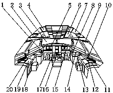
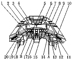
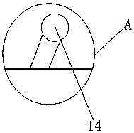
[0018] Such as Figure 1-4 As shown, a cockpit assembly includes a windshield 3 and a control button panel 17; A lifesaving rope storage place 7 is arranged between the dome lights 4, a sun visor 6 is fixedly installed on the outer surface of the lower end of the cabin dome light 4, a roller blind 9 is arranged below the co-pilot boom storage place 2, and a roller blind 9 is arranged below the roller blind 9. Air-conditioning outlet 10, the outer surface of the lower end of the air-conditioning outlet 10 is provided with a waste box 11 and a sundry storage place 12, the rear end outer surface of the waste box 11 is provided with a flight document storage place 20, and the outer surface of one side of the sundries storage place 12 is fixed Oxygen ...


PUM


Abstract

The invention discloses a driving cabin assembly. The assembly includes a windshield and a control button panel; co-pilot suspension rod depositories and cabin ceiling lights are fixedly installed onthe outer surface at the upper part of the windshield; lifesaving rope depositories are arranged between the co-pilot suspension rod depositories and the cabin ceiling lights; sun shields are fixedlyinstalled on the outer surfaces of the cabin ceiling lights; the lower parts of the co-pilot suspension rod depositories are provided with roller blinds; the lower parts of the roller blinds are provided with air-conditioning outlets; the outer surfaces on the lower ends of the air-conditioning outlets are provided with waste boxes and sundries depositories; and the outer surfaces on the rear endsof the waste boxes are provided with flight file depositories. Through the arrangement of sliding tray tables, the waste boxes and oxygen mask depositories, pilots can conveniently read and place files during driving and conveniently drop waste, emergency equipment can be put together for conveniently taking, and therefore, better using prospects can be brought.

Description

technical field [0001] The invention relates to the field of cockpit assemblies, in particular to a cockpit assembly. Background technique [0002] The cockpit assembly is an internal assembly of the cockpit that the pilot controls the aircraft. It is installed quickly and is easy to disassemble and replace. The cockpit is the head of the aircraft and is the center of order and control in the aircraft. The occupant feels comfortable to operate, and contains all the advanced navigation and various control systems used for air travel, just as important as other components that provide all the necessities of the occupant, it has been widely used, when in use due to internal There are many things, and the emergency equipment cannot be found in an emergency, which affects the driver to take the emergency equipment to get out of danger; the existing cockpit assembly has certain disadvantages when using it. First, the driver watches the flight documents and other paper materials. ...

Claims


Application Information

Patent Timeline
IPC IPC(8): B64C1/14B64D11/00B64D25/00
Inventor 张振扬
Owner 张振扬
Learn More