
Milling machine

a milling machine and machine body technology, applied in the field of milling machines, can solve the problems of limited machining capacity, inability to previously palletise workpieces, variable load moving along the work table, etc., and achieve the effects of saving floor space, high production capacity, and efficient machining

Active Publication Date: 2017-04-11
GEPRO SYST
View PDF16 Cites 0 Cited by
  • Summary
  • Abstract
  • Description
  • Claims
  • Application Information

AI Technical Summary

Benefits of technology

The solution enhances production capacity, reduces manufacturing costs, and minimizes material waste by enabling efficient machining of complex geometries with high precision and flexibility, while optimizing space usage and waste disposal.

Problems solved by technology

In both cases there is a limited machining capacity given that for parts of large dimensions a single head requires an extensive machining period.
In the case in which it is the work table that is moved, it is not possible to previously palletise the workpiece and therefore take full advantage of the capacity of the machine.
Another inconvenience is that the load moved along the work table is variable depending on the weight of the workpiece, and if this weight is high, it negatively affects the dynamics in the machining.
There are also known milling machines with work tables arranged in a horizontal plane which comprise more than one head, but the problem of said machines reside in the heavy structure which is necessary to be enable the heads to move on five axes, which makes said machines unsuitable to produce complex geometric parts, such as aeronautical parts, with high velocities and accelerations in order to achieve high productivity.
On the other hand, the heads of said machines keep the distance between them fixed, with the machining by panoplies not being possible, with the consequent waste of material and the increase of the production cost.
These configurations therefore carry a high number of unproductive movements, bringing an undesired increase in the manufacturing time and an inefficient use of the raw material.
These circumstances translate into cost increase of the machining process, and therefore a cost increase of the final product.
On the other hand there are disadvantages that the horizontal arrangement of the work surface brings.
One of them is the high occupied space which it entails and another is the difficult disposal of waste linked to the machining process.
On the other hand, machining the workpieces on a horizontal surface makes the disposal of the waste truly difficult, involving consumption of additional resources, or in other words, making the machining process more expensive.

Method used


Image

  • Milling machine
  • Milling machine
  • Milling machine

Examples


Embodiment Construction

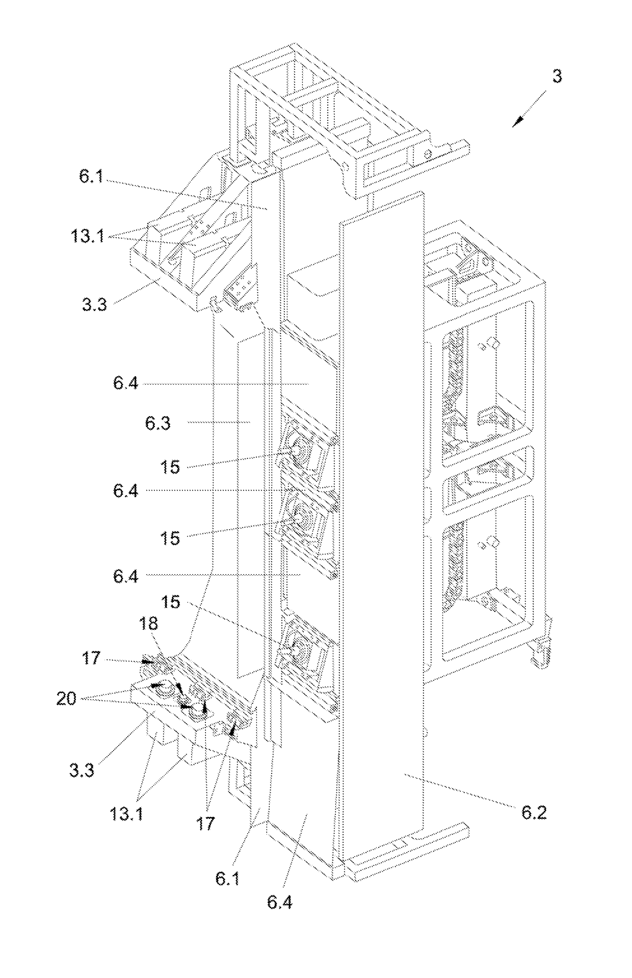
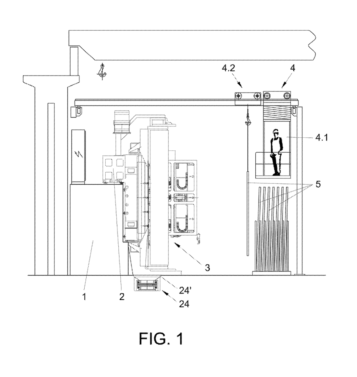
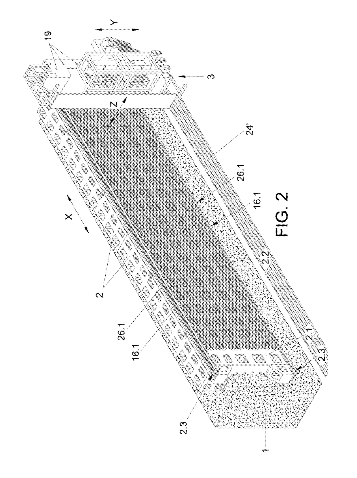
[0007]With the aim of achieving the objectives and avoiding the inconveniences mentioned in the previous sections, the invention proposes a milling machine that comprises a frame, which comprises a work surface arranged in a vertical plane, and a C-shaped moving bridge.

[0008]The present invention furthermore comprises at least three heads (7), each one of which comprises a machining spindle (15), and five movement axes, in such a way that the moving bridge is moved along the frame according to a horizontal axis, each head is independently moved on the moving bridge according to a vertical axis that is perpendicular to the horizontal axis, each head is moved on the moving bridge in order to be moved towards or moved away from the work surface according to a depth axis that is perpendicular to the horizontal axis and the vertical axis, and each head also independently performs rotating movements according to a first axis of rotation, and each machining spindle independently performs r...


PUM

PropertyMeasurementUnit
depthaaaaaaaaaa
weightaaaaaaaaaa
velocitiesaaaaaaaaaa

Abstract

A milling machine including a frame (2) having a work surface (2.1) disposed in a vertical plane and a C-shaped moving bridge (3). In addition, the machine includes: at least three heads (7), each head including a machining spindle (15); and five movement axes (X, Y, Z, A, B), such that the moving bridge (3) is moved by the frame (2) along a horizontal axis (X). Each head (7) is moved independently on the moving bridge (3) along a vertical axis (Y) in order to be moved towards or away from the work surface (2.1) along a depth axis (Z) perpendicular to both the horizontal axis (X) and the vertical axis (Y), as well as rotating independently about a first axis of rotation (A). Each spindle (15) rotates independently about a second axis of rotation (B).

Description

OBJECT OF THE INVENTION[0001]The present invention relates to a configuration and design of a milling machine with a work surface arranged in a vertical plane and a moving bridge, comprising a total of at least 3 heads, in order to provide high production capacity, efficient machining, saving floor space and easy waste disposal.BACKGROUND OF THE INVENTION AND TECHNICAL PROBLEM THAT IS RESOLVED[0002]Currently both the milling machines that comprise a single fastened head, with a work table arranged in a horizontal plane being the one that moves, as well as milling machines that comprise a single head, in this case moving, with the horizontally-arranged work table being the one which is kept fastened, are very well known. In both cases there is a limited machining capacity given that for parts of large dimensions a single head requires an extensive machining period. In the case in which it is the work table that is moved, it is not possible to previously palletise the workpiece and th...

Claims


Application Information

Patent Timeline
Patent Type & Authority Patents(United States)
IPC IPC(8): B23C1/04B23C1/00B23C1/12B23Q1/62B23Q1/26B23Q1/01B23Q1/54B23Q39/02B23Q5/32B23Q11/08B23Q39/00
CPCB23C1/04B23C1/002B23C1/007B23C1/12B23Q1/015B23Q1/26B23Q1/5406B23Q1/626B23Q39/024B23Q39/025B23C2220/32B23Q5/32B23Q11/08B23Q2039/002B23Q2039/006Y10T409/307672Y10T409/307784Y10T409/30392Y10T409/307896Y10T409/308232Y10T409/308344Y10T409/308568Y10T409/309576
Inventor ESTANCONA ERCILLA, JOSE ANTONIO
Owner GEPRO SYST
Learn More