
Packaging method for lithographic printing plate

Inactive Publication Date: 2005-04-07
FUJIFILM HLDG CORP +1
View PDF6 Cites 5 Cited by
  • Summary
  • Abstract
  • Description
  • Claims
  • Application Information

AI Technical Summary

Benefits of technology

[0015] The present invention is made in view of such circumstances, and has its object to provide a packaging method of lithographic printing plates which prevents deformation and peeling-off of films of the lithographic printing plates, is capable of setting the lithographic printing plates at an apparatus with a small operational burden, and further facilitates disposal of waste materials.
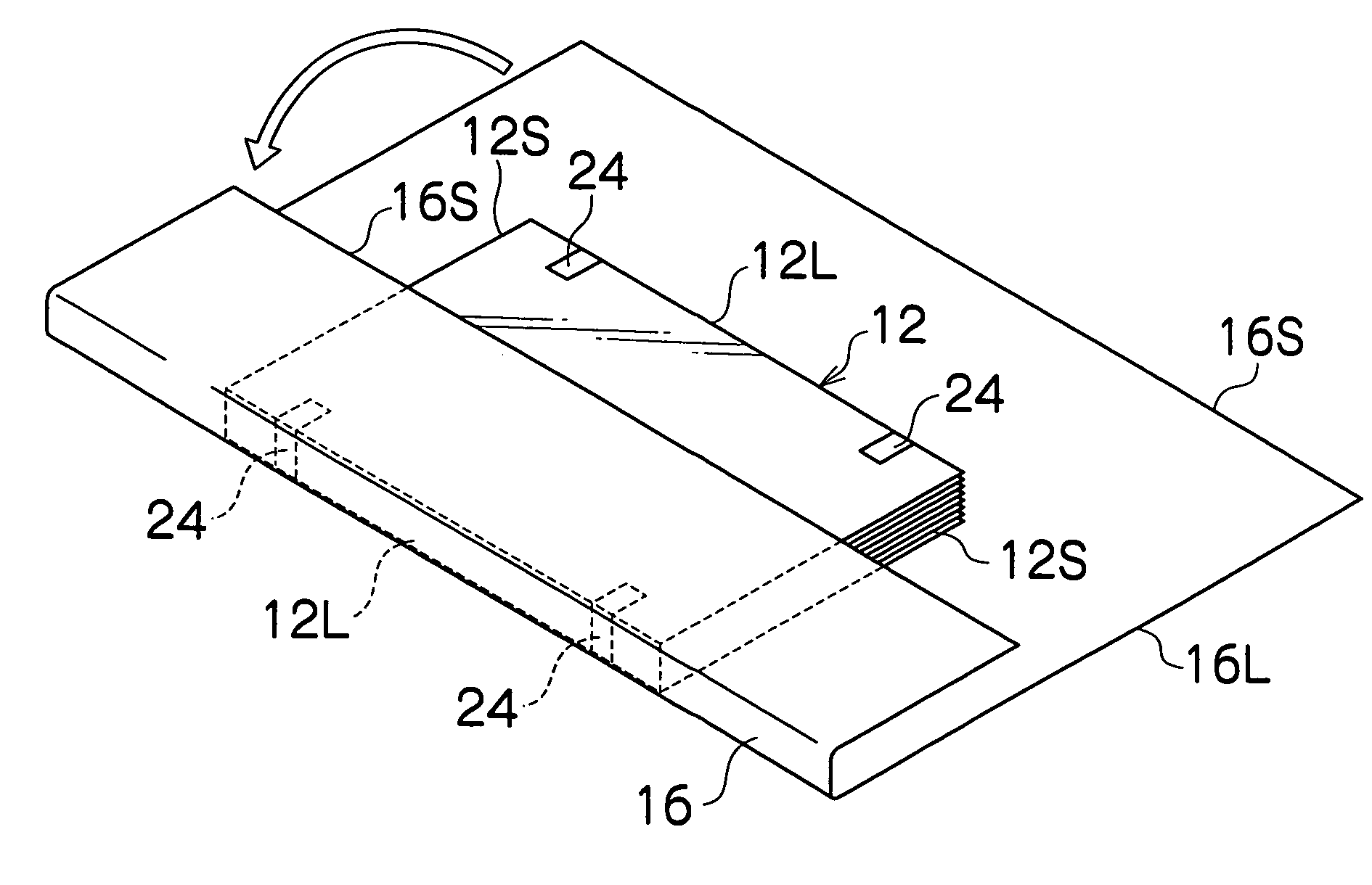
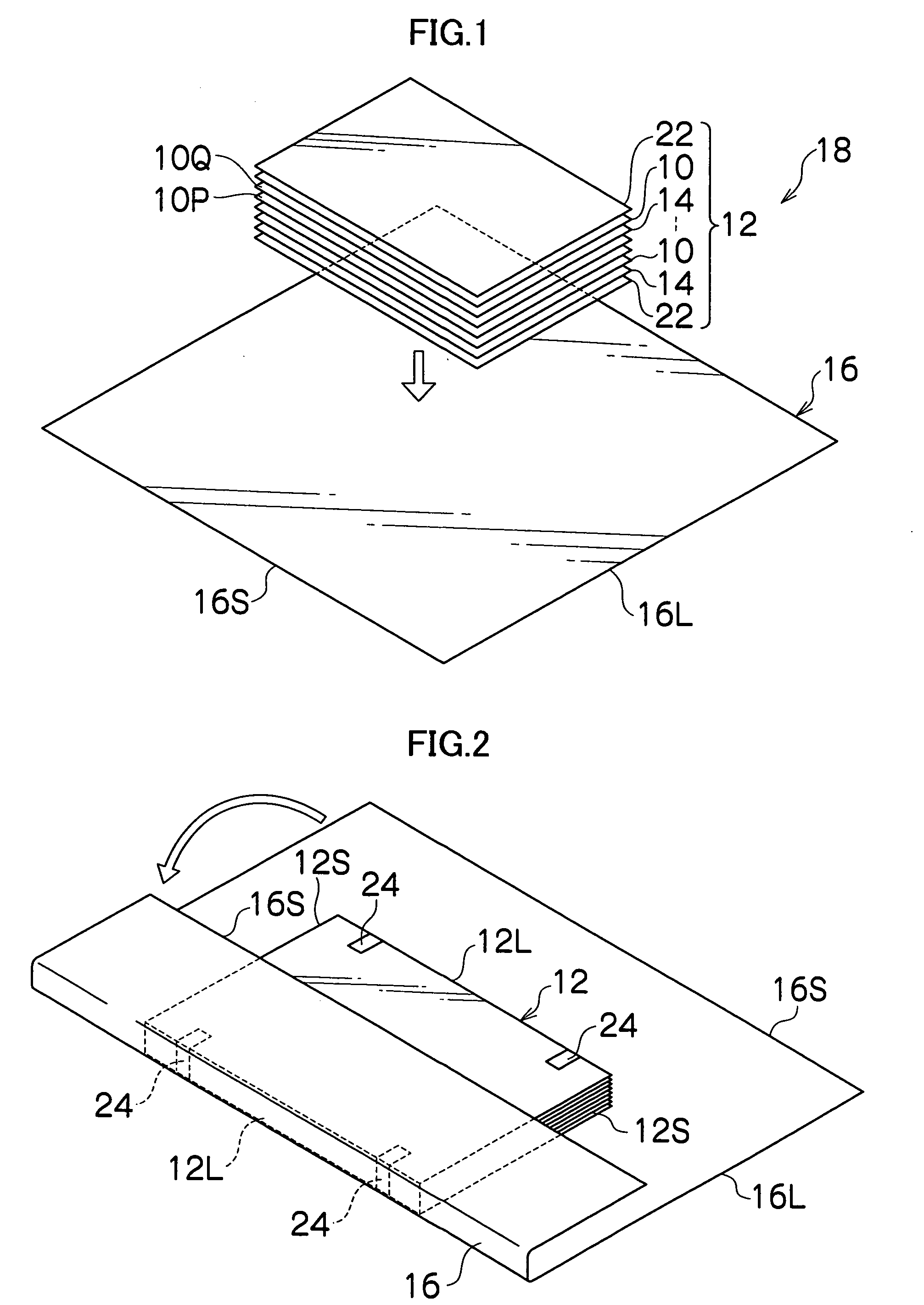
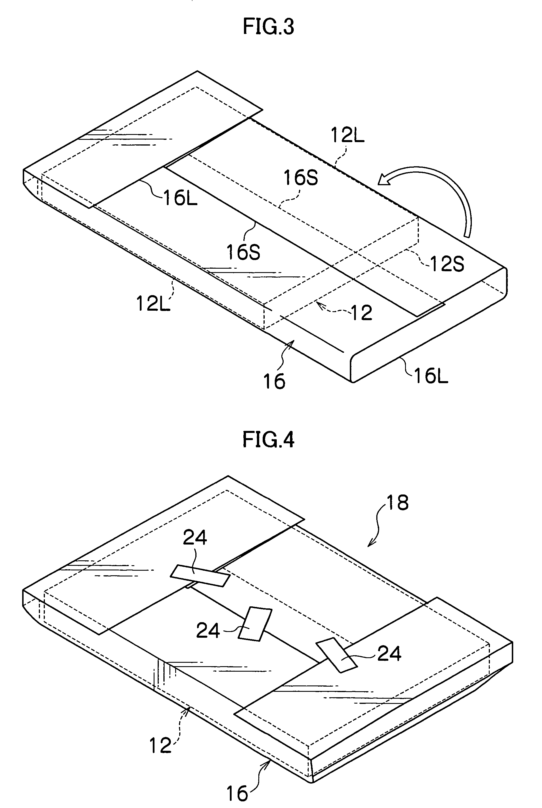
[0017] When the packing paper is unpacked, unpacking is performed with the unsealing surface facing upward. Since the lithographic printing plate is accommodated so that the image forming surface faces an opposite side from the unsealing surface of the packing paper, and therefore when the lithographic printing plate is taken out of the unsealing surface, the lithographic printing plate is taken out with the image forming surface facing downward. Accordingly, when the lithographic printing plate is set at the apparatus with the image forming surface facing downward, it is not necessary to invert the lithographic printing plate, and the operational burden on the user is reduced. Deformation of the lithographic printing plate and peeling-off of the film following the inverting operation do not occur. Since packaging is performed with only the packing paper, the unpacking operation can be performed easily, and disposal of the waste materials can be performed easily.
[0019] Generally, in the lithographic printing plate having an image forming surface constructed by such a recording layer, the coating film easily peels off and is damaged, but in the present invention, peeling-off of the film can be reliably prevented. In the lithographic printing plate having such a recording layer, it is possible to render an image directly on the image forming surface of the lithographic printing plate by emitting laser light.
[0020] According to the packaging method for the lithographic printing plate according to the present invention, since the lithographic printing plate is packaged so that the unsealing surface is on the opposite side from the image forming surface when the lithographic printing plate with only one side surface formed as the image forming surface is packaged with the packing paper, it is not necessary to invert the lithographic printing plate when the lithographic printing plate is set at the apparatus with the image forming surface facing downward, and therefore the operational burden on the user is reduced, thus eliminating deformation of the lithographic printing plate and occurrence of peeling-off of the film following the inverting operation. Packaging is only by the packing paper, and therefore the unpacking operation can be easily performed, thus making it possible to perform disposal of the waste materials easily.

Problems solved by technology

Accordingly, a user needs to set the lithographic printing plate at the apparatus by inversing the lithographic printing plate after unpacking the packing box 410, which becomes a large operational burden.
In addition, in order to prevent deformation and peeling off of the film of the lithographic printing plate like this, the user has to perform the operations of loading the lithographic printing plate into the apparatus and inverting the lithographic printing plate by paying close attention, which further increases the operational burden.
However, Japanese Patent Application Publication No. 2001-194774 and Japanese Patent Application Publication No. 2002-29173 have the problem that unpacking of the boxes are troublesome, and the boxes after unpacking are so bulky that it takes time and trouble to dispose of the boxes.

Method used


Image

  • Packaging method for lithographic printing plate
  • Packaging method for lithographic printing plate
  • Packaging method for lithographic printing plate

Examples


examples

[0119]FIG. 15 shows the test result of packaging by the packaging method according to the present invention. In the examples 1 to 3, packaging is performed under the conditions that the protective cardboard are inserted therein without outer boxes (namely, with only the packing paper 16), and the lithographic printing plates 10 are packaged so that the coated surface (corresponding to the image forming surface 10P) faces downward (namely, the coated surface is on the opposite side from the unsealing surface). In the examples 2 and 3, the packaged bodies are laid in a plurality of tiers as shown in the second to the fourth embodiments. Further, while individual packaging is performed in the examples 1 and 2, entire packaging is performed in the example 3.

[0120] On the other hand, the comparative examples 1 and 2 are the examples of packaging with the outer boxes without the protective cardboards. In the comparative example 2, packaging is performed so that the coated surface of the ...


PUM

PropertyMeasurementUnit
Solubility (mass)aaaaaaaaaa

Abstract

A packaging method for a lithographic printing plate for packaging by a packing paper the lithographic printing plate with only one side surface formed as an image forming surface, comprising the step of: packaging the lithographic printing plate with the packing paper so that an unsealing surface of the packing paper is on an opposite side from the image forming surface.

Description

BACKGROUND OF THE INVENTION [0001] 1. Field of the Invention [0002] The present invention relates to a packaging method for a lithographic printing plate, and particularly relates to a packaging method for a lithographic printing plate to package a lithographic printing plate with only one side surface formed as an image forming surface. [0003] 2. Description of the Related Art [0004] In a plate making method in recent years (including an electrophotographic plate making method), lithographic printing plates such as a photosensitive printing plate and a thermosensitive printing plate are widely used to facilitate automation of a plate making process. A lithographic printing plate is generally produced by performing surface treatments such as, for example, graining, anodic oxidation, silicate treatment, and other conversion treatments individually or suitably in combination for a substrate such as a sheet-shaped or coil-shaped aluminum plate, then by performing coating of a photosens...

Claims


Application Information

Patent Timeline
IPC IPC(8): B41N3/00G03F7/00B41N6/00B65B11/00B65B11/48B65B25/14B65D75/04B65D77/00G03C3/00
CPCG03F7/0012G03C3/00
Inventor USUI, TAKAYUKI
Owner FUJIFILM HLDG CORP
Learn More