
Cable tunnel micro automatic fireproof door

A technology for cable tunnels and fire doors, applied in the field of fire doors, can solve the problems of increased fire extinguishing costs, human inspection dangers, losses, etc., and achieve the effects of avoiding human and material investment, avoiding further expansion, and saving fire extinguishing costs.

Active Publication Date: 2019-06-25
芜湖扬进自动化设备科技有限公司
View PDF8 Cites 1 Cited by
  • Summary
  • Abstract
  • Description
  • Claims
  • Application Information

AI Technical Summary

Problems solved by technology

[0002] Cable tunnel refers to a corridor or tunnel-like structure used to accommodate a large number of cables laid on cable supports. For the convenience of construction, maintenance and inspection, there are generally pedestrian maintenance roads in the tunnel, and a fire door is set tens of meters apart. In the event of a fire, it is used to prevent the penetration and spread of flames and reduce property losses. The space of the cable tunnel is narrow and long, usually about 1.8 m high and 1.5 m wide. In some places where the cable replacement is less, the width and height are less than 1 m In these places, due to the small space, human inspection is very dangerous and inconvenient, so robots will be used instead of manual inspections. Most of the existing fire doors for robots are simple and have single functions. It has the effect of further extinguishing the fire, and the practicability is poor. In addition, most fire doors are only equipped with a single sensor, which is prone to misjudgment when alarming, which leads to unnecessary losses and increases the cost of fire extinguishing.

Method used


Image

  • Cable tunnel micro automatic fireproof door
  • Cable tunnel micro automatic fireproof door
  • Cable tunnel micro automatic fireproof door

Examples


Embodiment Construction

[0022] The following will clearly and completely describe the technical solutions in the embodiments of the present invention with reference to the accompanying drawings in the embodiments of the present invention. Obviously, the described embodiments are only some, not all, embodiments of the present invention. Based on the embodiments of the present invention, all other embodiments obtained by persons of ordinary skill in the art without making creative efforts belong to the protection scope of the present invention.

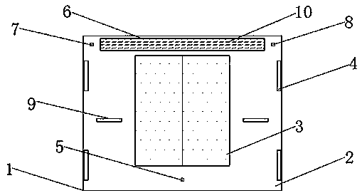
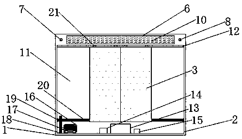
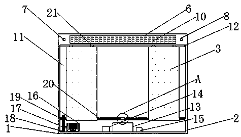
[0023] see Figure 1-6 , the present invention provides a technical solution: a cable tunnel miniature automatic fire door, including fire door body 1, door frame 2, door leaf 3, fixed plate 4, SN04-P proximity sensor 5, groove 6, MQ-2 smoke sensor 7. ZJM-6 flame sensor 8, lighting lamp 9, glass cover 10, storage cavity 11, chute 12, storage battery 13, ARM microprocessor 14, wireless transceiver module 15, R280 motor 16, rotating shaft 17, driving gear 18 , ...


PUM


Abstract

The invention discloses a cable tunnel micro automatic fireproof door. A door frame is arranged on the outside of a fireproof door body, a groove is separately formed in two sides of the middle part of the top end of the door frame, a fire extinguishing agent is filled into the interior of each groove, a glass cover is mounted on the outside of the grooves, fixing boards are mounted on the upper and lower ends of the two sides of the door frame, the two sides of the interior of the door frame are provided with accommodation cavities, sliding chutes are formed on the top ends of the accommodation cavities, door leaves are mounted on the inner sides of the accommodation cavities, an R280 electromotor is mounted on the lower left corner of the interior of the door frame, one end of the R280 electromotor is fixedly connected with a rotation shaft, a driving gear is mounted on one end of the rotation shaft, a driven gear is engaged with the top of the driving gear, and a screw is mounted inthe middle part of the driven gear. According to the cable tunnel micro automatic fireproof door, the grooves are clamped with the glass cover, operation is simple, installation and disassembly are convenient, the glass cover can be replaced when being damaged after a fire disaster, simplicity and practicability are realized, and later maintenance cost of the fireproof door body is reduced.

Description

technical field [0001] The invention relates to the technical field of fire doors, in particular to a miniature automatic fire door of a cable tunnel. Background technique [0002] Cable tunnel refers to a corridor or tunnel structure used to accommodate a large number of cables laid on cable supports. For the convenience of construction, maintenance and inspection, there are generally pedestrian maintenance roads in the tunnel, and a fire door is set tens of meters apart. In the event of a fire, it is used to prevent the penetration and spread of flames and reduce property losses. The space of the cable tunnel is narrow and long, usually about 1.8 m high and 1.5 m wide. In some places where cables are less replaced, the width and height are less than 1 m In these places, due to the small space, human inspection is very dangerous and inconvenient, so robots will be used instead of manual inspections. Most of the existing fire doors for robots are simple and have single funct...

Claims


Application Information

Patent Timeline
IPC IPC(8): E21F17/103E21F17/18E05F15/72A62C37/10G08B21/24
Inventor 倪秀英
Owner 芜湖扬进自动化设备科技有限公司
Learn More