Non-bearing and full-medium-operated split type solar water heater
A solar water heater, non-pressurized technology, applied to solar collectors, solar collector shells, solar collector heat insulation, etc., can solve medium circulation pipeline rupture, medium circulation pipeline leakage, medium circulation pipe Road corrosion and other problems, to avoid manpower and material resources, reduce the cost of use, improve the effect of service life
- Summary
- Abstract
- Description
- Claims
- Application Information
AI Technical Summary
Problems solved by technology
Method used
Image
Examples
Embodiment 1
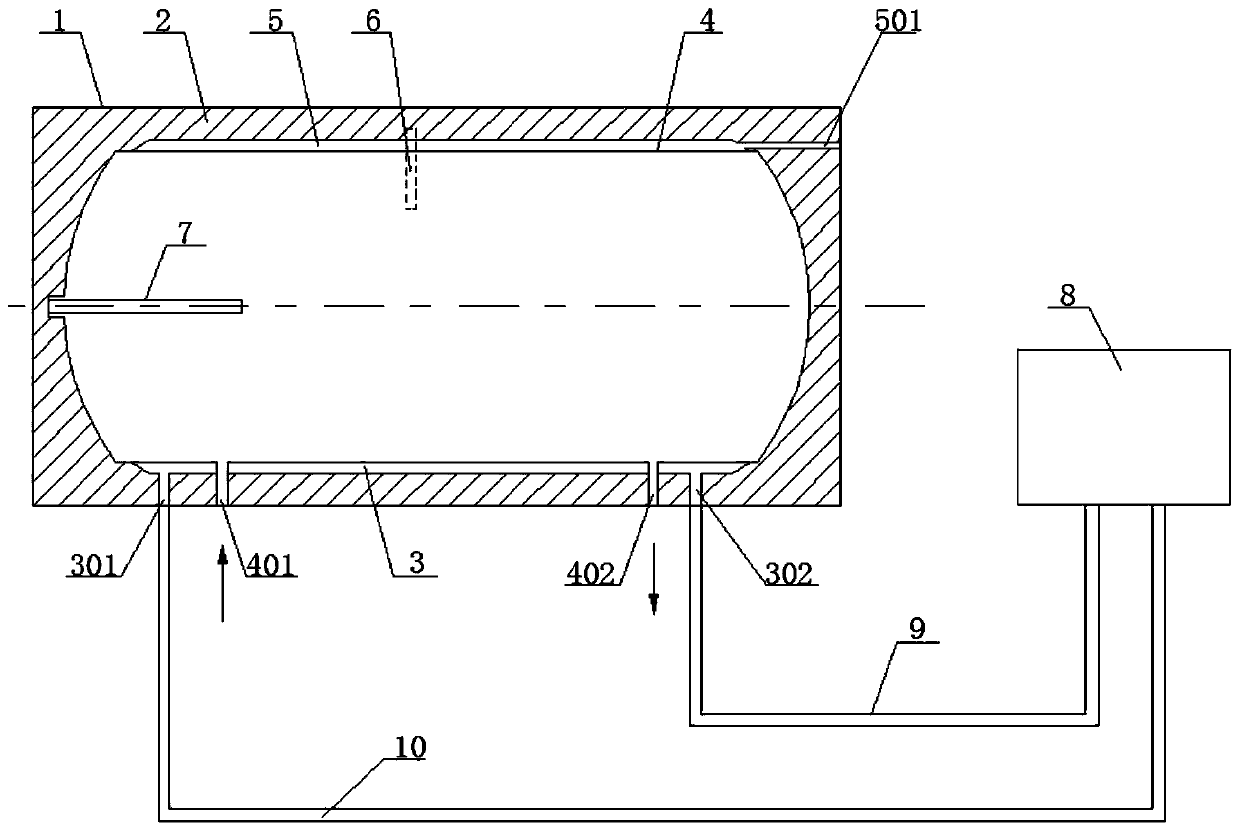
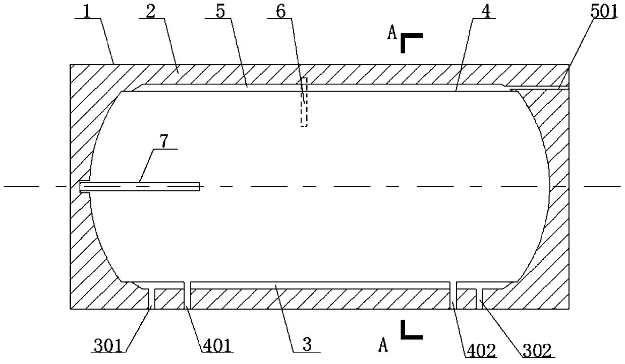
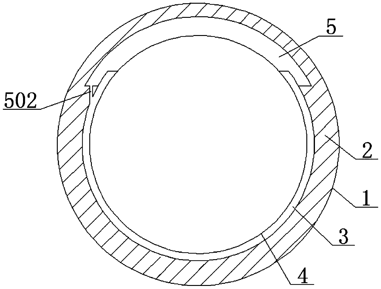
[0044] Such as Figure 1-4 As shown, a non-pressurized split solar water heater with full medium operation includes a horizontal solar water tank, and the horizontal solar water tank includes a tank, a heat exchange jacket 3 , an inner tank 4 , and a buffer sleeve 5 . The box body includes an outer shell 1 and an insulating layer 2 arranged coaxially from the outside to the inside. The box body, the heat exchange jacket 3, and the liner 4 are coaxially arranged in sequence from the outside to the inside, and the heat exchange jacket 3 communicates with the heat collector 8 to form a closed medium circulation pipeline, specifically: the heat exchange jacket 3 passes through the medium The inlet pipe 9 and the medium outlet pipe 10 communicate with the heat collector 8 to form a closed medium circulation pipeline.
[0045] Such as image 3 As shown, the heat exchange jacket 3 only wraps two-thirds of the inner tank 4, and the heat exchange jacket 3 wraps the lower half of the ...
Embodiment 2
[0056] This embodiment 2 is the same as embodiment 1, the difference is that, as Figure 6 and Figure 7 As shown, the water tank is a vertical solar water tank, and the heat exchange jacket 3 wraps half to all of the inner tank 4. In this embodiment 2, the heat exchange jacket 3 wraps the middle and lower parts of the inner tank 4, and the buffer sleeve 5 Set above the heat exchange jacket 3, that is, the buffer sleeve 5 is set at the place where the inner tank 3 is not wrapped by the heat exchange jacket 3, specifically: as Figure 7 As shown, the buffer sleeve 5 is in the shape of a ring cylinder.
Embodiment 3
[0058] This embodiment 3 is the same as embodiment 2, the difference is that, as Figure 8 and Figure 9 As shown, the heat exchange jacket 3 wraps the cylindrical part of the inner tank 4 , the upper and lower hemispherical parts of the inner tank 4 are not wrapped by the heat exchange jacket 3 , and the buffer sleeve 5 is arranged in the insulation layer 2 . Specifically: such as Figure 8 As shown, the buffer sleeve 5 is arranged in the upper left corner of the thermal insulation layer 3. Of course, the buffer sleeve 5 can also be arranged in the upper right corner of the thermal insulation layer 2. The height of the connecting end of the buffer jacket 5 is even, and the connecting end of the connecting pipe 502 and the heat exchanging jacket 3 is arranged on the upper end of the heat exchanging jacket 3 .
[0059] By arranging the buffer sleeve 5 in the thermal insulation layer 2, not only the area of the inner tank 4 wrapped by the heat exchange jacket 3 can be enlarg...
PUM
 Abstract
Description
Claims
Application Information
 - R&D
- Intellectual Property
- Life Sciences
- Materials
- Tech Scout
- Unparalleled Data Quality
- Higher Quality Content
- 60% Fewer Hallucinations
Browse by: Latest US Patents, China's latest patents, Technical Efficacy Thesaurus, Application Domain, Technology Topic, Popular Technical Reports.
© 2025 PatSnap. All rights reserved.Legal|Privacy policy|Modern Slavery Act Transparency Statement|Sitemap|About US| Contact US: help@patsnap.com


