
Method for manufacturing high-loading electrode

A high-load, electrode technology, used in electrode manufacturing, battery electrodes, final product manufacturing, etc., can solve problems such as uneven dispersion, floating on the surface, and de-embedding, and achieve the effect of preventing floating

Active Publication Date: 2019-06-25
LG ENERGY SOLUTION LTD
View PDF16 Cites 1 Cited by
  • Summary
  • Abstract
  • Description
  • Claims
  • Application Information

AI Technical Summary

Problems solved by technology

[0007] In this structure, if the thickness of the electrode layer is increased to increase the capacity of the battery, the lithium ion transport path becomes longer, lithium intercalation / deintercalation into / from the active material far from the current collector occurs, and the movement of electrons through the current collector is restricted
Also, since the binder contained in the electrode layer is relatively light, it is not uniformly dispersed in the electrode layer, and a phenomenon of floating on the surface occurs
The thicker the electrode layer, the greater this separation, so deterioration of battery cycle characteristics and reduction in battery life due to separation of the current collector and active material generated during charging / discharging cannot be avoided
[0008] In addition, when a large amount of slurry is placed on the current collector and dried, a part of the slurry is not dried, or if it is hit, problems such as electrode layer damage at the corner and electrode strength decrease due to increased electrode layer thickness The problem

Method used


Image

  • Method for manufacturing high-loading electrode
  • Method for manufacturing high-loading electrode
  • Method for manufacturing high-loading electrode

Examples


Embodiment 1

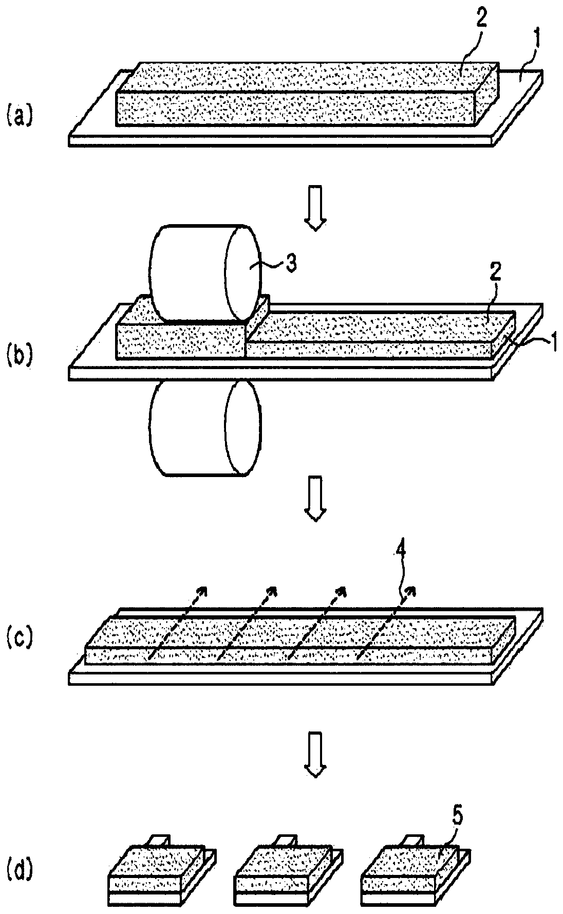
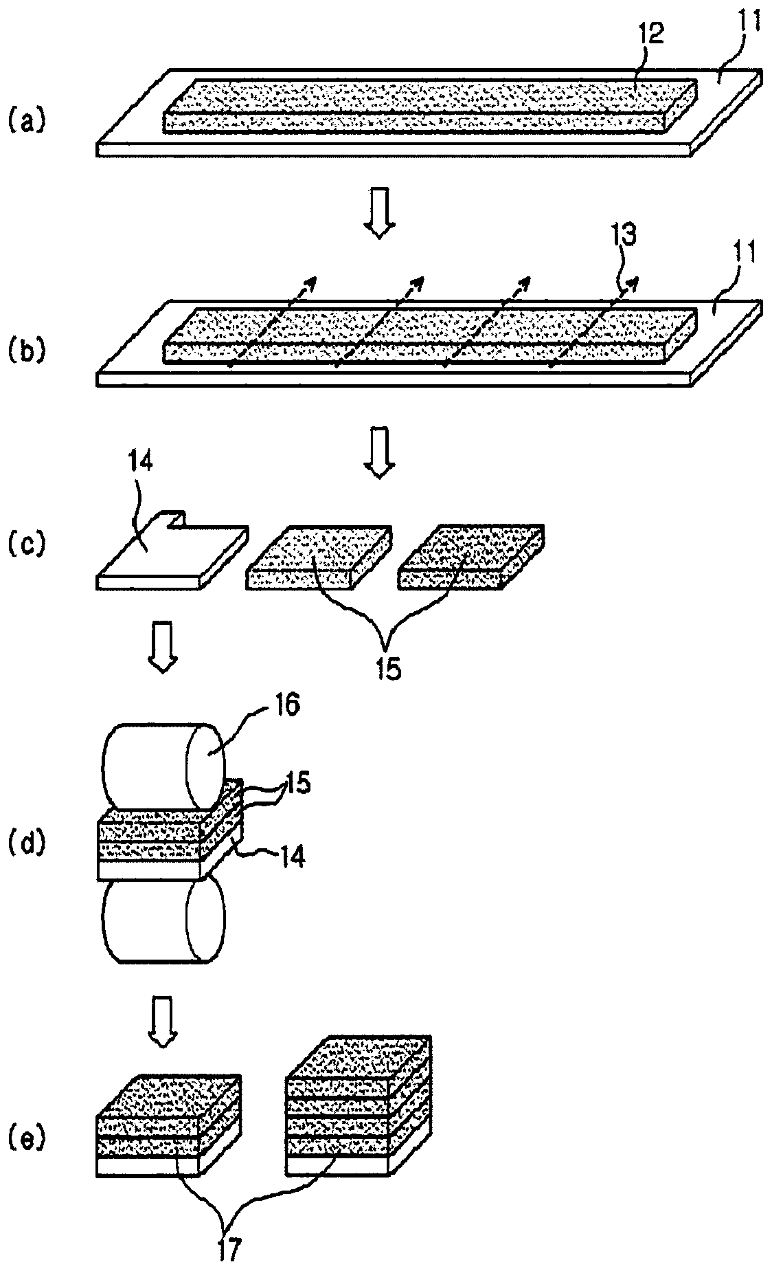
[0063] Will LiNi 0.55 mn 0.30 co 0.15 o 2 (positive electrode active material), Danka black (denka black, conductive agent) and polyvinylidene fluoride (PVDF) (binder) were mixed in a weight ratio of 96:2:2, and then NMP (N-methylpyrrolidone ) to make slurry. The slurry was applied on a PET film to make an electrode layer. The thickness of the electrode layer was set to 120 μm. The electrode layer was punched out in a unit electrode size and the release film was removed, which was then placed in 2 layers on an aluminum foil current collector and rolled to produce a positive electrode.

[0064] An electrode assembly was fabricated using the fabricated positive electrode, and then the electrode assembly was placed in an aluminum pouch and connected to an electrode lead. Thereafter, will contain 1M LiPF 6 The carbonate-based composite solution is injected into the electrolyte, and then sealed to assemble a lithium secondary battery.

Embodiment 2 to 8

[0066] A positive electrode and a lithium secondary battery were manufactured in the same manner as in Example 1 except having the thicknesses and the number of layers shown in Table 1 below.

Embodiment 9

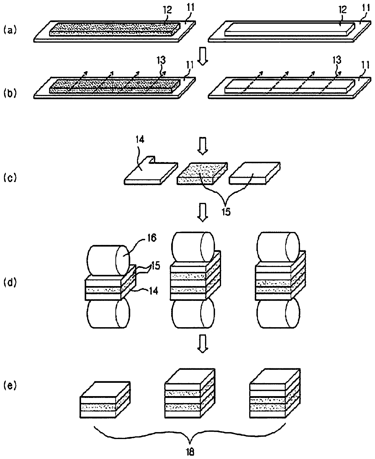
[0068] Will LiNi 0.55 mn 0.30 co 0.15 o 2 (cathode active material), Danka black (conductive agent) and polyvinylidene fluoride (PVDF) (binder) are mixed in a weight ratio of 96:2:2, and then NMP (N-methylpyrrolidone) is added to manufacture slurry. The slurry was applied on the PET film to make the first electrode layer. The thickness of the first electrode layer was set to 120 μm.

[0069] LiCoO 2 (positive electrode active material), Danka black (conductive agent) and polyvinylidene fluoride (PVDF) (binder) are mixed in a weight ratio of 80:5:15, and then NMP (N-methylpyrrolidone) is added to manufacture slurry. The slurry was applied on a PET film to make a second electrode layer. The thickness of the second electrode layer was set to 120 μm.

[0070] The first electrode layer and the second electrode layer were punched out in a unit electrode size and the release film was removed, and were alternately placed on an aluminum foil current collector to form a total o...


PUM

PropertyMeasurementUnit
thicknessaaaaaaaaaa
thicknessaaaaaaaaaa
thicknessaaaaaaaaaa

Abstract

Provided is a method for manufacturing a high-loading electrode, which prevents a phenomenon in which a binder lifts off from an electrode layer, prevents a problem when drying an electrode slurry from occurring, and prevents a problem of damage of the electrode layer and reduction in electrode strength at corner portions in blanking from occurring. The method for manufacturing a high-loading electrode comprises: a step of applying an electrode slurry to a release film to manufacture an electrode layer having the release film attached thereto; a step of blanking the electrode layer having therelease film attached thereto to the size of a unit electrode; and a step of separating and removing the release film from the blanked electrode layer, and then stacking and rolling the electrode layer on a current collector in two or more layers.

Description

technical field [0001] The present disclosure relates to a method of manufacturing a highly loaded electrode, and more particularly, to a method of manufacturing a highly loaded electrode by applying an electrode slurry on a release film to produce a The electrode layer of the film, punching the electrode layer with the release film attached to the size of a unit electrode, and separating and removing the release film from the punched electrode layer, and then placing the electrode layer on the At least two layers are placed on the current collector and calendered. Background technique [0002] With the development of mobile device technology and the increase in demand for mobile devices, the demand for secondary batteries as energy sources is rapidly increasing. In recent years, secondary batteries are currently used as power sources for electric vehicles (EV) and hybrid vehicles (HEV), and in particular, there is a high demand for lithium secondary batteries having high e...

Claims


Application Information

Patent Timeline
Patent Type & Authority Applications(China)
IPC IPC(8): H01M4/04H01M4/139H01M4/13H01M10/0525H01M2/10
CPCH01M4/04H01M4/13H01M4/139H01M10/0525Y02E60/10H01M4/0435H01M4/0402H01M2004/021H01M2220/30H01M2220/20Y02P70/50H01M50/204H01M50/247H01M50/249H01M50/251H01M2220/10
Inventor 闵智媛金锡九金容俊杰尼施·德勒朴世美
Owner LG ENERGY SOLUTION LTD
Learn More