Biological experiment test tube batch detoxification device
A biological experiment and generating device technology, which is applied in the field of biological experimental test tube batch disinfection devices, to achieve good cleaning effect, good cleaning and sterilization effect, and good sterilization effect
Inactive Publication Date: 2019-06-28
THE AFFILIATED HOSPITAL OF QINGDAO UNIV
8 Cites 4 Cited by
AI-Extracted Technical Summary
Problems solved by technology
[0003] The invention provides a batch disinfection device for biological experiment test tubes. The rotating scrubbing device can effectively cooperate with the ultrasonic treatment device to stir the solution so that the small bubbles generated by the ultrasonic wave can better adhere to the solute, and at the same time, the solute that is loose and oscillating ...
Method used
As shown in Figure 2, 6, 9, ultrasonic treatment device 4 comprises ultrasonic generator 17 and ultrasonic treatment device support 41, ultrasonic circuit connection end 42, treatment device accommodating part 43, accommodating Part connecting rod 44, probe part connecting rod 45, probe part screw adjustment knob 46, ultrasonic probe part 47, vibrator 48, the ultrasonic processing device 4 is fixed on the upper bottom surface 22 bottom of the upper box body 1 bottom box body by the ultrasonic processing device bracket 41 On the fixed platform 241 of the device, the command signal is transmitted to the ultrasonic circuit connection end 42 by the ultrasonic generator 17, released by the processing device accommodating part 43 containing the ultrasonic element in front of the ultrasonic circuit connection end 42, and then through the probe part connecting rod 45, The connecting rod 45 of the probe part to the vibrator 48 at the front end of the ultrasonic probe part 47 forms a high-frequency vibration. The ultrasonic probe part 47 is extended to the bottom of the test tube, and the action end of the ultrasonic treatment device 4 and the rotary scrubbing device 3 are arranged on the same axis. The ultrasonic processing device 4 acts on each test tube alone, which can prevent the existing ultrasonic cleaning equipment from unbalanced action in the test tube bucket, making the ultrasonic effect more stable. The ultrasonic processing device 4 acts vertically on the test tube, which can make cavitation The air bubbles are better in contact with the test tube, which can make the cavitation bubbles attach more bacteria.
As shown in Figure 2, support platform adjustment device 8 comprises support platform rotating device 81, support platform lifting device 82, support platform rotating device 81 can make test tube base 265 drive test tube 10 horizontal rotation, support platform lifting device 82 can The test tube base 265 drives the test tube 10 to move up and down. The supporting table rotating device 81 comprises a base fixed end 811, a supporting table rotating rod 812, a motor rotating gear 813, a supporting table rotating motor 814, and a supporting table rotating gear 815, and the test tube base 265 is fixed on the supporting table by the base fixed end 811 The rotating rod 812, the end of the supporting table rotating rod 812 is connected with the supporting table rotating gear 815, and the motor rotating gear 813 fixedly connected with the front end of the supporting table rotating motor 814 is engaged with the supporting table rotating gear 815. The supporting table lifting device 82 includes a rotating device box fixed end 821, a supporting table lifting rod 822, a first connecting shaft 823, a second connecting shaft 824, a hydraulic jack connecting end 825, a hydraulic jack 826, a hydraulic jack base 82...
Abstract
The invention provides a biological experiment test tube batch sterilization device. The device comprises an upper box body and a lower box body, a rotary washing device, an ultrasonic treatment device, a high-pressure steam treatment device and a supporting table adjusting device are arranged in the box body, the high-pressure steam treatment device and the supporting table adjusting device are used for adjusting the position of the test tube in an up-and-down and rotating manner, and the rotary washing device rotates at the upper part of the test tube and is used for cleaning the test tube together with the ultrasonic treatment device on the same axis. By means of the rotary washing device arranged in the device, the test tube opening can be effectively cleaned, meanwhile, the action effect of the ultrasonic treatment device is enhanced by washing water stirred in the test tube, the supporting table adjusting device is used for moving the test tube, so that a plurality of sets of cleaning equipment are cooperatively used, and the effect is improved. The device has the advantages that the size is small, the cleaning effect is better, the test tube capable of effectively cleaning the complex biological solute, and meanwhile, the technical problems that the test tube is poor in cleaning and disinfecting effects and the like are avoided.
Application Domain
Hollow article cleaningCleaning using liquids +1
Technology Topic
Test tubeBiomedical engineering +2
Image
Examples
- Experimental program(1)
Example Embodiment
[0035] The present invention will be further explained below through the drawings and embodiments.
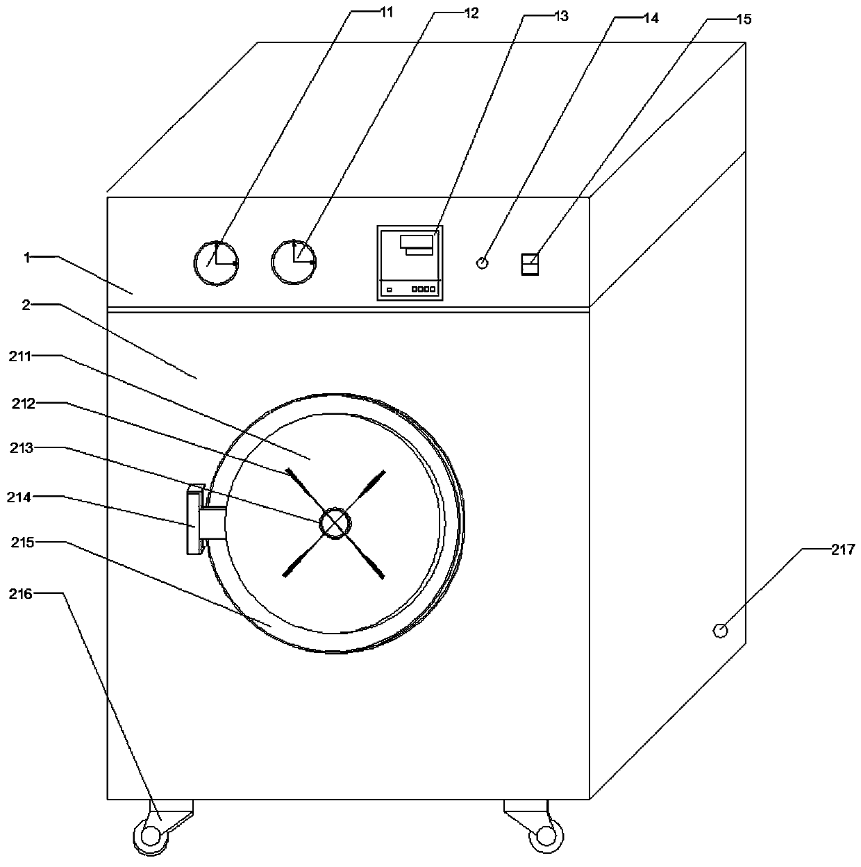
[0036] Such as figure 1 As shown, the biological experiment test tube batch disinfection device of the present invention includes an upper box body 1 and a lower box body 2. The box body is provided with a rotating scrubbing device 3, an ultrasonic processing device 4, a high-pressure steam processing device 5, and a support platform adjusting device 8. UV generating device 7, preheating device 6. There are thermometer 11, pressure gauge 12, operating controller 13, display lamp 14, switch button 15 outside the upper box 1, the switch button 15 can control the device to turn on or off, when the device is turned on, according to different processing stages, display The lamp 14 will have different color changes. The operation controller 13 controls the high-pressure steam treatment time, ultrasonic and rotary scrubbing treatment time, ultraviolet switch, preheating time and other related procedures of the device. During the high-pressure steam treatment process, the pressure gauge 12 The pressure in the lower tank 2 is displayed, and the temperature in the lower tank 2 is displayed by the thermometer 11. The outside of the lower box body is provided with a sealed box door 211, a box door twisting hand gate 212, a box door twisting hand gate shaft 213, a sealed box door shaft 214, a magnetic door frame 215, a box wheel 216, and a water outlet 217, passing through the box door The rotating handle on the twisting hand gate 212 can be rotated together with the box door rotating hand gate shaft 213 to open or close the sealed box door 211. The closed box door 211 can be rotated horizontally by the sealed box door shaft 214, and the magnetic sealing frame 215 can be matched The sealed box door 211 achieves a good sealing effect, the box wheel 216 can drive the box to move on the ground, and the water outlet 217 provided on the side of the lower box 2 can discharge the water in the waste water collection tank 97 in the high-pressure steam generator 9.
[0037] Such as Figure 2-3 , 9-11, inside the upper box 1 is provided with a PLC micro-controller 16, an ultrasonic generator 17, a steam generation controller 18, and a rotating linkage motor 311 of the rotating scrubbing device 3. The signal is transmitted to the PLC micro-controller 16 through the operation controller 13 outside the upper box 1, and the PLC micro-controller 16 is provided with a PLC display screen 161 and a PLC program button 162 at the same time. The PLC display screen 161 is used to display the recorded running program , PLC program button 162 is used to adjust the specific program of the device. The PLC microcontroller 16 sends command signals to the rotary scrubbing device 3, the ultrasonic treatment device 4, the high-pressure steam treatment device 5, the support table adjusting device 8, the ultraviolet generating device 7, and the preheating device 6. The steam generation controller 18 includes a steam generation control display 181 and a steam generation control adjustment switch 182. The steam generation control display 181 is used to record and store operating data. The steam generation control adjustment switch 182 can open or close the steam generation controller 18. The ultrasonic generator 17 includes an ultrasonic frequency display 171, an ultrasonic adjustment button 172, an ultrasonic switch 173, and a water collection tank 183. The ultrasonic frequency display 171 is used to record and store operating data. The ultrasonic adjustment button 172 can manually adjust the ultrasonic frequency and size. The ultrasonic switch 173 The ultrasonic switch 173 can be turned on and off, and the water collection tank 183 is used to store cleaning liquid and at the same time to collect waste liquid.
[0038] On the bottom surface 22 of the upper box 1 is fixed with an upper device fixing table 241 and a lower device fixing table 242 by a device fixing table screw assembly 23. The device fixing table screw assembly 23 includes a fixing table nut 231 and a fixing table screw 232 , Fix the nut 233 under the table, the nut 231 on the fixing table fix the screw 232 of the fixing table on the upper bottom surface 22 of the bottom box of the upper box 1, and fix the upper fixing table 241 of the device through the screw, and fix the nut 233 on the lower table. The lower bottom surface of the lower fixing table 242 of the device is provided with a lower bottom surface 27 of the box body under the upper bottom surface 22 of the box body. The lower bottom surface 27 of the box body is provided with a test tube base 265. The test tube base 265 passes through the test tube support table screw assembly 26 A test tube upper support 251 and a test tube lower support 252 are fixed. The test tube support screw assembly 26 includes a support upper nut 261, a support screw 262, a support lower nut 263, a test tube base nut 264, and a test tube base nut 264 The supporting table screw 262 is fixed to the test tube base 265, the test tube lower supporting table 252 is fixed to the supporting table screw 262 by the supporting table nut 263, the test tube upper supporting table 251 is fixed to the supporting table screw 262 by the supporting table nut 261, the test tube base A rotating device box 28 is fixed at the lower part of the 265, and a supporting table rotating device 81 is provided in the rotating device box 28.
[0039] Such as Figure 4-5 , 10, the rotary scrubbing device 3 includes a rotary linkage device 31, a rotary scrubbing device 32, the rotary linkage device 31 and the rotary scrubber device 32 are connected by teeth, the rotary linkage device 31 includes a rotary linkage motor 311, a rotary linkage motor bracket 312, The rotary linkage rod 313, the rotary gear connecting end 314, the linkage rod rotary gear 315, and the rotary gear fixing button 316. The rotary linkage motor 311 is fixed by a rotary linkage motor bracket 312 provided on the upper bottom surface 22 of the bottom case in the upper case 1, The rotary linkage motor 311 is connected with a rotary linkage rod 313. The rotary linkage rod 313 passes through the upper fixing table 241, and is connected to the linkage rod rotation gear 315 through the rotary gear connecting end 314 provided at the front end of the rotary linkage rod 313, and is fixed by the rotary gear The button 316 is fixed. The rotating scrubbing device 32 is provided with a scrubbing device rotating gear 321, a scrubbing device support portion 322, a scrubbing bucket 323, and a hair brush 324. The scrubbing device support portion 322 fixes the rotating scrubbing device 32 on the lower fixing table 242, and the rotating scrubbing device The scrubbing device rotation gear 321 on 32 is engaged with the linkage lever rotation gear 315 provided on the rotation linkage device 31. A scrubbing bucket 323 is arranged under the scrubbing device rotation gear 321, and the scrubbing bucket 323 extends to the upper third to half of the test tube In one place, a plurality of rows of brushes 324 are evenly distributed on the scrubbing bucket 323. The brushes 324 are in contact with the inner wall of the test tube. The rotation linkage motor 311 provided by the rotation linkage device 31 drives the rotation linkage rod 313 with the linkage rod rotation gear 315 installed. , The rotating gear 321 of the scrubbing device installed on the rotating scrubbing device 32 drives the brush 324 on the scrubbing bucket 323 on the device to rotate, and the cleaning solution in the test tube is driven by the brush 324 to flow and scrub the tube wall. Through the rotation of the rotary scrubbing device 3, the test tube mouth can be cleaned and disinfected to prevent secondary pollution of the test tube opening in the traditional cleaning process. At the same time, the rotating scrubbing device 3 can rotate the cleaning solution to make the subsequent ultrasonic treatment device 4 generate cavitation. The air bubbles more fully act on the tube wall, and the sterilization effect is better. At the same time, the rotation of the water flow is helpful to wash the solute loosened by the ultrasonic on the tube wall.
[0040] Such as figure 2 , 6 As shown in 9, the ultrasonic treatment device 4 includes an ultrasonic generator 17 and an ultrasonic treatment device holder 41, an ultrasonic circuit connection end 42, a treatment device receiving portion 43, a receiving portion connecting rod 44, and a probe connection The rod 45, the probe part screw adjustment knob 46, the ultrasonic probe part 47, and the vibrator 48 are used to fix the ultrasonic treatment device 4 on the device upper fixing table 241 at the bottom of the upper case 1 through the ultrasonic treatment device bracket 41, The command signal is transmitted to the ultrasonic circuit connection terminal 42 through the ultrasonic generator 17, and released through the processing device accommodating portion 43 that houses the ultrasonic element in front of the ultrasonic circuit connection terminal 42, and then to the ultrasonic probe via the probe connecting rod 45 and the probe connecting rod 45 The vibrator 48 at the tip of the portion 47 forms a high-frequency vibration, and the ultrasonic probe portion 47 is provided with a probe portion screw adjustment knob 46 that can expand and contract the length of the ultrasonic probe portion 47. The ultrasonic probe part 47 is extended to the bottom of the test tube, and the active end of the ultrasonic treatment device 4 and the rotary scrubbing device 3 are arranged on the same axis. The ultrasonic treatment device 4 acts on each test tube separately, which can prevent the existing ultrasonic cleaning equipment from being unbalanced in the test tube barrel, and make the ultrasonic effect more stable. The ultrasonic treatment device 4 acts on the test tube vertically to make cavitation. The bubbles are in better contact with the test tube, which can make the cavitation bubbles attach more bacteria.
[0041] Such as figure 2 , 7 As shown in -9, the high-pressure steam treatment device 5 includes a high-pressure steam acting end 50 and a high-pressure steam generating device 9. The high-pressure steam acting end 50 is arranged on the upper bottom surface 22 of the bottom of the upper box 1, and the high-pressure steam generating device 9 is arranged on the bottom. At the rear of the box 2, the high-pressure steam output by the high-pressure steam generator 9 can act in the test tube at the high-pressure steam acting end 50. The high-pressure steam action end 50 is provided with a water collection tank 183, a steam generation controller 18, a high-pressure steam treatment device bracket 51, a high-pressure steam connection end 52, a high-pressure steam screw connection button 53, a connection button connection rod 54, a high-pressure steam differentiation connection rod 55, Water spray nozzle connecting rod 561, spray nozzle elbow 562, spray nozzle head 563, steam head connecting rod 571, steam head connecting screw port 572, steam head connecting button 573, steam nozzle 574, high-pressure steam action end 50 through The high-pressure steam treatment device bracket 51 is fixed on the device upper fixing table 241 at the lower part of the upper bottom surface 22 of the bottom of the upper box 1, and the command signal is transmitted to the high-pressure steam connection terminal 52 through the steam generation controller 18, and is connected by the high-pressure steam screw Button 53, connecting button connecting rod 54, high-pressure steam differentiation connecting rod 55 Differentiation steam device and spraying solution device, the spraying solution device is connected to the spray nozzle elbow 562 through the spray nozzle connecting rod 561, the spray nozzle is bent A spray gun head 563 is installed at the front end of the tube 562. The solution spraying device is connected to the water collecting tank 183 in the upper tank 1, and the solution is delivered to the spray gun head 563 of the solution spraying device through the water collecting tank 183, so that the test tube Full of solution. At the same time, the spraying solution device can also absorb waste liquid and high-pressure vapor liquefied water, so that the test tube is in an anhydrous and dry state. The steam device is fixed to the steam head connecting button 573 through the installed steam nozzle 574, and is connected to the steam head connecting thread 572 on the steam head connecting rod 571, and sprays high-pressure steam to the inner wall of the test tube 10 through the steam nozzle 574.
[0042] The high-pressure steam generating device 9 includes a steam generator 91, a steam pressurizing pump 93, a pressurizing pump valve 94, a surge tank 95, a clean water pump 96, and a waste water collection tank 97. The steam generator 91 generates hot steam in the steam pressurizing pump The pressure in 93 is pressurized, and the pressure is stabilized and output to the high-pressure steam action end 50 in the surge tank 95 through the pressurizing pump valve 94. The waste water collection tank 97 collects the wastewater in the surge tank 95 and the water collecting tank 183 in the high-pressure steam treatment device 5. The steam generator 91 includes a steam tank seal 911, a steam tank body 912, a steam tank pressure gauge 913, a steam tank heating pipe 914, a steam heating pipe connecting rod 915, a steam heating pipe base 916, a steam tank level gauge 917, and a steam tank Support feet 918, steam valve 92, pure water enters the steam tank body 912 through the lower part of the steam tank body 912, and passes through the steam tank set on the steam heating pipe connecting rod 915 at the upper part of the steam heating pipe base 916 at the bottom of the steam tank body 912 The heating pipe 914 is heated, and the steam generated by heating is output through the steam tank seal 911 on the top of the steam tank body 912. The steam tank pressure gauge 913 is used to display the pressure inside the steam tank body 912, and the steam tank level gauge 917 is used for detection. The height of the water level inside the steam tank body 912. The steam tank support feet 918 can smoothly fix the steam tank body 912 on the ground. A steam valve 92 is provided on the output pipe to control the output of steam in the steam tank body 912. speed. The produced steam is pressurized by the steam pressurizing pump 93, and then the flow rate of the pressurized steam is controlled by the pressurizing pump valve 94. The pressurized steam passes through the pressurizing pump valve 9 and enters the surge tank 95 for voltage stabilization. The surge tank 95 includes Surge tank pressure gauge 951, surge tank seal 952, surge tank body 953, surge tank support feet 954, a surge tank seal 952 is set above the surge tank body 953 for repairing tanks and tanks The lower part of the body is provided with a surge tank support foot 954, and a surge tank pressure gauge 951 is arranged on the tank body to detect the vapor pressure in the surge tank. The high-pressure steam is output to the high-pressure steam acting end 50 through the surge tank. The steam condensed water generated at the bottom of the surge tank is transported to the waste water collection tank 97 through the pipeline through the clean water pump 96. The waste water collection tank 97 includes the waste water collection tank seal 971, the waste water collection tank body 972, the waste water collection tank level gauge 973, and the waste water outside. Drain valve 974, waste water collection tank support foot 975, the upper end is connected with a water collection tank 174, the waste water collection tank seal 971 is used to check and repair the waste water collection tank 97, the waste water is collected in the waste water collection tank body 972, waiting to pass the level of the waste water collection tank When the meter 973 detects that the waste water reaches a certain height, the waste water discharge valve 974 is opened to drain the water. The spray gun head on the high-pressure steam action end can spray or absorb the cleaning solution, which can spray the cleaning solution and absorb the waste liquid after the action of the rotating scrubbing device and the ultrasonic treatment device. At the same time, it can absorb the liquid condensed in the test tube by the high-pressure steam to realize the test tube. The entire cleaning process can be completed without leaving the box. The high-pressure steam device can effectively kill the bacteria in the test tube, and at the same time use the steam blowing process to achieve the cleaning effect on the tube wall.
[0043] Such as figure 2 As shown, the supporting platform adjusting device 8 includes a supporting platform rotating device 81 and a supporting platform lifting device 82. The supporting platform rotating device 81 can make the test tube base 265 drive the test tube 10 to rotate horizontally, and the supporting platform lifting device 82 can make the test tube base 265 drive The test tube 10 moves up and down. The supporting table rotating device 81 includes a base fixing end 811, a supporting table rotating rod 812, a motor rotating gear 813, a supporting table rotating motor 814, and a supporting table rotating gear 815. The test tube base 265 is fixed to the supporting table through the base fixing end 811 The end of the rotating rod 812 and the supporting platform rotating rod 812 is connected to the supporting platform rotating gear 815, and the motor rotating gear 813 fixedly connected to the front end of the supporting platform rotating motor 814 is engaged with the supporting platform rotating gear 815. The support platform lifting device 82 includes a rotating device box fixed end 821, a support platform lifting rod 822, a first connecting shaft 823, a second connecting shaft 824, a hydraulic jack connecting end 825, a hydraulic jack 826, a hydraulic jack base 827, and a rotating device The fixed end of the box body 821 connects the support platform lifting rod 822 to the bottom of the rotating device box 28. The lower end of the support platform lifting rod 822 is connected with the first connecting shaft 823 and the second connecting shaft 824, and connects with the hydraulic The top 826 is connected. With the support adjustment device 8 provided, the horizontal rotation and up and down movement of the test tube can be realized, so that the test tube can cooperate with each other and flexibly switch between the devices.
[0044] First, the high-pressure steam is sent to the high-pressure steam action end 50 through the high-pressure steam generator 9, and sprayed to the inner wall of the test tube 10 through the steam nozzle 574. After the high-pressure steam action is completed, the high-pressure steam in the test tube 10 is liquefied by the nozzle 563. The water is sucked out, and then the cleaning solution is sprayed through the spray gun head 563. When the cleaning solution is filled with two-thirds to four-fifths of the liquid level of the test tube, the spraying is stopped. The test tube base 265 is moved down by the support platform lifting device 82 of the support platform adjustment device 8 until it is lower than the height of the working end of the cleaning equipment, and then the support platform rotation device 81 is activated to rotate the test tube 10 to the rotating scrubbing device 3 and the ultrasonic treatment device 4 Acting on the axis, that is, rotate 30°, start the support platform lifting device 82 again to raise the test tube base 265 until the vibrator 48 of the ultrasonic treatment device 4 is close to the bottom of the test tube 10, start the rotating scrubbing device 3 and the ultrasonic treatment device 4, wait After the cleaning of the rotating scrubbing device 3 and the ultrasonic treatment device 4 is completed, they pass through the support platform lifting device 82 and the support platform rotating device 81 of the support platform adjusting device 8 again, so that the test tube returns to the high-pressure vapor action end 50, and the spray gun head 563 The waste liquid in the test tube 10 is sucked out, and finally the test tube base 265 is lowered by the support platform lifting device 82, and the test tube 10 is taken out to complete the cleaning and disinfection process.
[0045] Preferably, a nano titanium dioxide catalyst or a hydrogen peroxide solution is added to the cleaning solution used by the device. The nano titanium dioxide catalyst can synergistically enhance the effect of ultrasound, and titanium dioxide can enhance the ultraviolet sterilization effect of the cleaning and disinfecting device.
[0046] Such as figure 2 As shown, the ultraviolet generating device 7 includes an ultraviolet circuit connection end 71, an ultraviolet generating sheet 72, a generating device bracket 73, an ultraviolet lamp fixing end 74, and a lamp tube 75. The ultraviolet lamp fixing end 74 is fixed on the generating device bracket 73 and is connected with The upper bottom surface 22 of the box body 1 is fixedly connected, the UV lamp fixed end 74 is connected with the lamp tube 75 and the UV circuit connection terminal 71, and the UV circuit connection terminal 71 is connected with an ultraviolet generating sheet 72. The ultraviolet light has a good sterilization effect. The ultraviolet generating device 7 can further sterilize the box and the test tube 10 after the processing by the rotating scrubbing device 3 and the ultrasonic processing device 4 is completed, thereby avoiding secondary pollution to the test tube that may be caused in the subsequent cleaning process.
[0047] The preheating device 6 includes a heating tube connection bracket 61, a heating tube connection button 62, a heating tube terminal 63, and a heating tube 64. The heating tube connection bracket 61 is fixedly arranged on the side walls of the left and right sides of the lower box, and is wired through the heating tube. The heating tube 64 connected to the heating tube connecting button 62 under the head 63 preheats the lower box body 2 so as to effectively prevent the test tube from directly contacting the high-pressure steam and easy to cause explosion.
[0048] The test tube cleaning and sterilizing device can effectively kill bacteria and viruses in the test tube 10, and several groups of cleaning equipment can be used together by moving the test tube 10, reducing the volume of the cleaning and sterilizing device, and the cleaning effect is better. It has a good cleaning and anti-virus effect on test tubes that are difficult to routinely handle.
[0049] The above embodiments give a limited range of examples to illustrate the present invention in detail. It cannot be considered that the embodiments of the present invention are limited to this. For those of ordinary skill in the art to which the present invention belongs, everything made according to the spirit of the present invention Any simple modification and equivalent structural transformation or modification belong to the protection scope determined by the claims submitted by the present invention.
PUM


Description & Claims & Application Information
We can also present the details of the Description, Claims and Application information to help users get a comprehensive understanding of the technical details of the patent, such as background art, summary of invention, brief description of drawings, description of embodiments, and other original content. On the other hand, users can also determine the specific scope of protection of the technology through the list of claims; as well as understand the changes in the life cycle of the technology with the presentation of the patent timeline. Login to view more.
Similar technology patents
Medical apparatus cleaning device
Owner:佛山市翠微自动化科技有限公司
Washing control method for washing machine
Owner:QINGDAO HAIER WASHING MASCH CO LTD
Environment-friendly waterborne industrial cleaning agent with low COD (Chemical Oxygen Demand) value
Owner:重庆信人科技发展有限公司
Path navigation method of robot driving on rectangular slope
Owner:SUZHOU RADIANT PHOTOVOLTAIC TECH
Classification and recommendation of technical efficacy words
- good cleaning effect
- Equipment is small
Push-type wall skin removing device for building construction
Owner:民发现代建设工程集团有限公司
Metallic material surface detergent
Owner:JIANGSU HAIXUN IND GROUP SHARE
Electrooxidation treatment technique for wastewater of chlorobenzene-containing compound
Owner:ZHEJIANG UNIV OF TECH
Test system used for satellite power supply and distribution system
Owner:AEROSPACE DONGFANGHONG SATELLITE
Method of producing hydroxy free radical from reaction of ozone and exutad water
Owner:DALIAN MARITIME UNIVERSITY
Self-driving tour control system and method based on unmanned plane
Owner:XIDIAN UNIV
Flaky medium conveying mechanism
Owner:GRG BAKING EQUIP CO LTD