Automobile subframe crossbeam positioning and welding device

A positioning device and positioning welding technology, used in auxiliary devices, welding equipment, welding equipment and other directions, can solve the problems of inaccurate cavity size of parts, difficulty in manual retrieval, affecting product quality, etc., to prolong service life and connect quickly. , the effect of reducing the burden on workers

Inactive Publication Date: 2019-06-28
广西源龙新能源车辆有限公司
View PDF0 Cites 3 Cited by
  • Summary
  • Abstract
  • Description
  • Claims
  • Application Information

AI Technical Summary

Problems solved by technology

Usually, when welding, the process hole of the lower plate is first aligned with the fixed positioning pin on the tooling, and then the upper plate is inserted at the position of the mounting hole to ensure the height of the beam cavity; but in the actual welding process, due to The plate is deformed by heat, and after the beam of the sub-frame is welded as a whole, the thermal stress deformation causes the beam to interfere with the positioning pin on the tooling, making it difficult to manually pick up the piece, which affects work efficiency; due to the thermal deformation of the plate, the plugs inserted in the cavity of the beam Blocks are difficult to remove, affecting work efficiency, and even lead to inaccurate part cavity dimensions, affecting product quality

Method used


Image

  • Automobile subframe crossbeam positioning and welding device
  • Automobile subframe crossbeam positioning and welding device
  • Automobile subframe crossbeam positioning and welding device

Examples


Embodiment

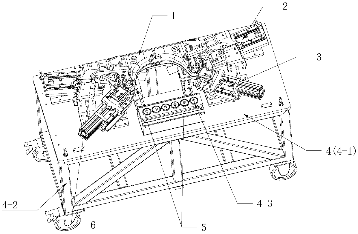
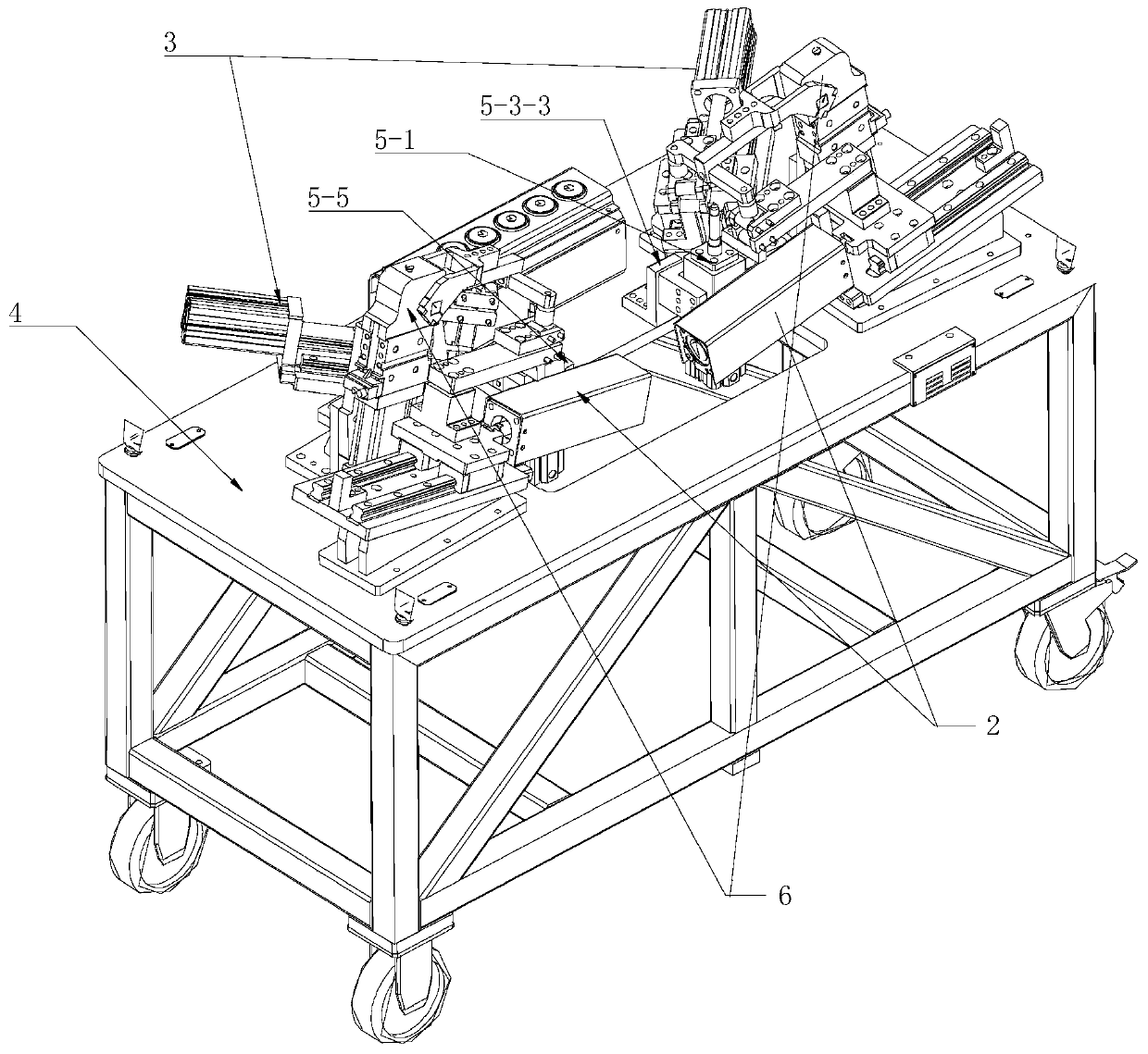
[0047] See figure 1 with figure 2 , a positioning welding device for an automobile sub-frame beam, comprising a base device 4, a first positioning device 5, a second positioning device 2, a third positioning device 3 and a clamping device 6, the first positioning device 5, the second positioning device The positioning device 2 , the third positioning device 3 and the clamping device 6 are all mounted on the base device 4 . The automobile subframe 1 is positioned and fastened on the first positioning device 5 through the first positioning device 5 , the second positioning device 2 , the third positioning device 3 and the clamping device 6 .

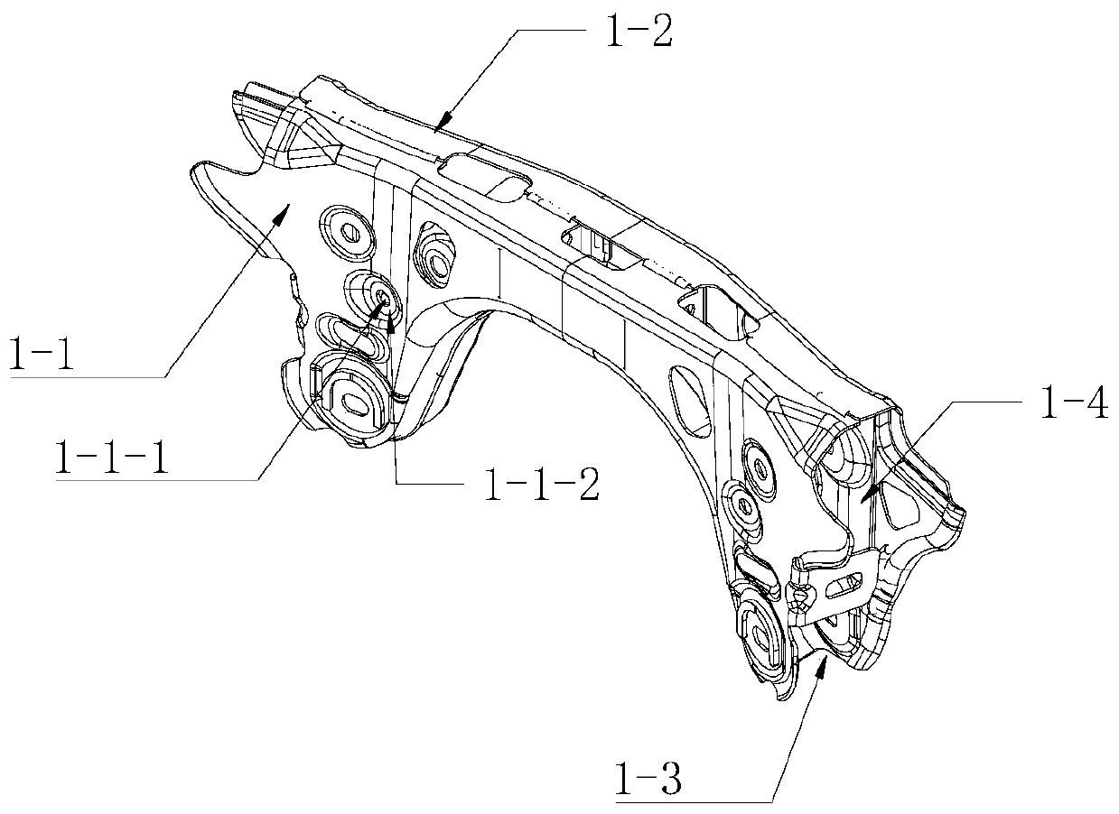
[0048] Such as image 3 , the automobile subframe 1 includes a subframe upper plate 1-1 and a subframe lower plate 1-2, wherein the subframe upper plate 1-1 is provided with an upper plate positioning hole 1-1-1, and the upper plate is positioned The surrounding plane of the hole 1-1-1 is the upper plate positioning surface 1-1-2 (inne...


PUM


Abstract

The invention discloses an automobile subframe crossbeam positioning and welding device and belongs to the technical field of tooling equipment. The device comprises a first positioning device, a second positioning device, a third positioning device and a clamping device which are all arranged on a base device. The first positioning device comprises a main pin positioning mechanism and an auxiliary pin positioning mechanism, the main pin positioning mechanism comprises a telescopic pin pushing air cylinder, a telescopic pin air cylinder mounting support, a main positioning pin and a main pin guide block, the telescopic pin air cylinder mounting support is installed on the base device, the telescopic pin pushing air cylinder penetrates through a cavity of the telescopic pin air cylinder mounting support, the main positioning pin is connected with the end of a connecting rod of the telescopic pin pushing air cylinder through a mounting groove R at the end of the main positioning pin, themain pin guide block is fastened to the end face of the telescopic pin air cylinder mounting support, and a positioning block I is further arranged on one side surface of the telescopic pin air cylinder mounting support. According to the automobile subframe crossbeam positioning and welding device, difficult part mounting caused by over-positioning can be prevented, part damage and tool abrasionare prevented, the working efficiency is improved, and the service life is prolonged.

Description

【Technical field】 [0001] The invention relates to the technical field of tooling equipment, in particular to a positioning welding device for a crossbeam of an automobile sub-frame. 【Background technique】 [0002] The sub-frame beam of the automobile is a hollow body welded by two upper and lower thin plate stamping parts. The sub-frame beam has mounting holes connected with the swing arm and shock absorber, so the height of the cavity of the sub-frame beam (ie The space distance between the upper and lower plates) will affect the installation of the swing arm and shock absorber. Usually, when welding, the process hole of the lower plate is first aligned with the fixed positioning pin on the tooling, and then the upper plate is inserted at the position of the mounting hole to ensure the height of the beam cavity; but in the actual welding process, due to The plate is deformed by heat, and after the beam of the sub-frame is welded as a whole, the thermal stress deformation c...

Claims


Application Information

Patent Timeline
Patent Type & Authority Applications(China)
IPC IPC(8): B23K31/02B23K37/04
CPCB23K31/02B23K37/0443Y02T10/40
Inventor 张雄黄楚峰杨奕思詹咪
Owner 广西源龙新能源车辆有限公司
Why Eureka
Try Eureka