Clean water tank suction well system and use method thereof

A technology of water absorption wells and clear water pools, applied in the configuration of water supply pools, water supply devices, buildings, etc., can solve problems such as high water level self-irrigation start-up pumps with low buried depth, inconvenient personnel to patrol up and down, and poor ventilation conditions in pump rooms, etc. , to achieve the effect of improving the disinfection effect, reducing the buried depth, and reducing the cost of the project

Pending Publication Date: 2019-06-28
BEIJING GENERAL MUNICIPAL ENG DESIGN & RES INST
View PDF11 Cites 4 Cited by
  • Summary
  • Abstract
  • Description
  • Claims
  • Application Information

AI Technical Summary

Problems solved by technology

[0005] The present invention provides a clean water pool suction well system and its use method, the purpose of which is to solve the energy waste caused by the drop of water flow in the process of supplying the water from the waterworks to the city water terminal in the prior art, and the inability to achieve high water level in the prior art The self-irrigation start causes the water pump to have a low burial depth, which in turn causes problems such as high engineering cost, poor ventilation conditions in the pump room, poor heat dissipation conditions of the motor, and inconvenience for personnel to patrol up and down.

Method used


Image

  • Clean water tank suction well system and use method thereof
  • Clean water tank suction well system and use method thereof
  • Clean water tank suction well system and use method thereof

Examples


Embodiment Construction

[0026] The specific embodiments of the present invention will be further described below in conjunction with the drawings.

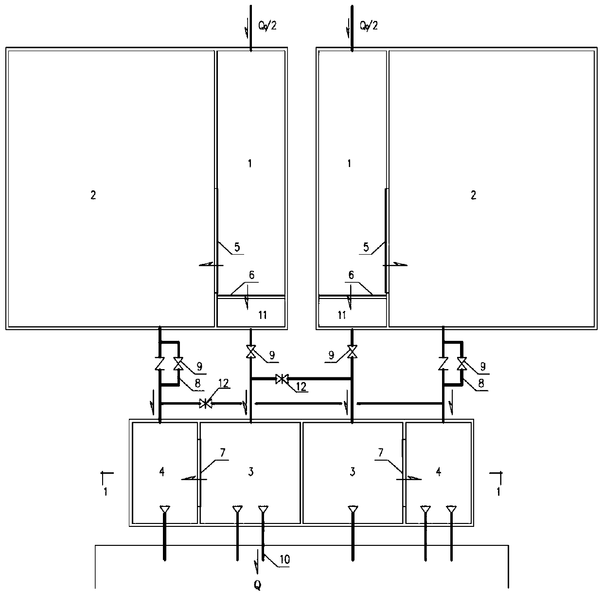
[0027] See attached figure 1 , A clean water suction well system, including a chlorination contact tank 1, a clean water tank 2, a main suction well 3, an auxiliary suction well 4, an anti-backflow device 8, a flow regulating valve 9, a water pump suction pipe 10, and a water outlet well 11;

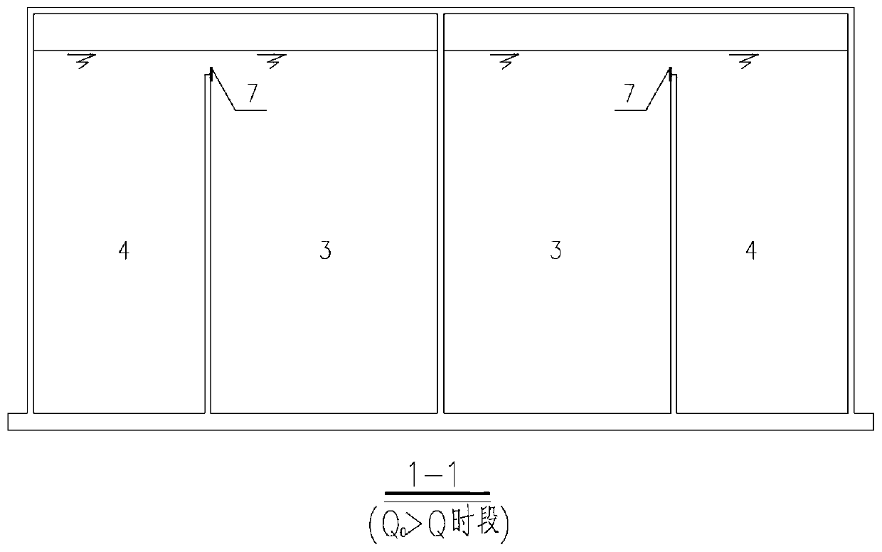
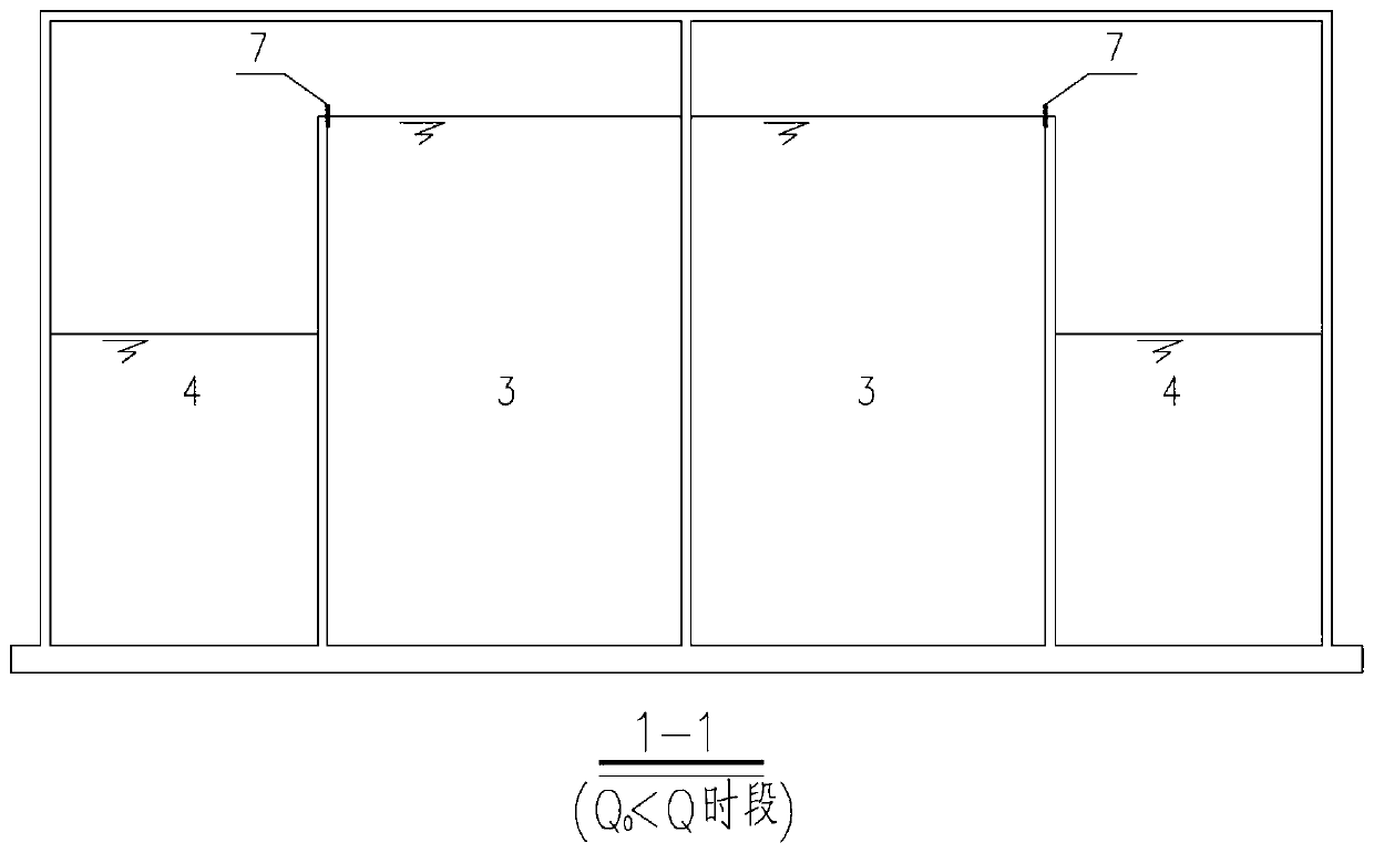
[0028] The chlorination contact tank 1 communicates with the clean water tank 2 through a high weir 5, and the chlorination contact tank 1 communicates with the outlet well 11 through a low weir 6 provided above. The outlet well 11 The main suction well 3 is communicated with the main suction well 3 through a pipeline and the flow is adjusted by the flow regulating valve 9, the main suction well 3 is communicated with the auxiliary suction well 4 through the low weir two 7, the high weir 5, the low weir one 6. The two low weirs 7 are arranged in order from high to low; ...


PUM


Abstract

The invention discloses a clean water tank water suction well system and a using method thereof. The clean water tank water suction well system comprises a chlorine adding contact tank, a clean watertank, a main water suction well, an auxiliary water suction well, an anti-backflow device, a flow regulating valve and a water pump water suction pipe, wherein the chlorine adding contact tank is communicated with the clean water tank through a high weir; the chlorine adding contact tank is communicated with the main water suction well through a low weir I; the outlet well is communicated with themain suction well through a pipeline and the flow is regulated through a flow regulating valve, the main suction well is communicated with the auxiliary suction well through the low weir II, the highweir, the low weir I and the low weir II are sequentially arranged from high to low, the clean water tank is communicated with the auxiliary suction well through a backflow prevention device to supply water for the auxiliary suction well, and the main suction well and the auxiliary suction well are respectively externally connected with a plurality of water pump suction pipes to supply water forthe city. According to the clean water tank suction well system and the use method thereof, the energy consumption is saved, the chlorination disinfection effect is improved, the high-water-level self-irrigation starting is realized under the condition that a vacuum pump is not arranged, the operation management is convenient, the construction cost is reduced, the ventilation condition of a pump room is improved, and the personnel patrol is more convenient.

Description

Technical field [0001] The invention relates to a clean water pool suction well system and a use method thereof, which are used in the water supply field of a clean water pool and a water distribution pump house suction well in a water purification plant. Background technique [0002] The existing water purification plant clean pool and suction well process is that all purified water enters the clean pool, and after the clean pool is adjusted and stored, it enters the water distribution pump room suction well, and then the pump sucks water from the suction well to supply city water. Since the water intake of the clean water pond is uniform, while the urban water use is uneven, the clean water pond needs a certain adjustment volume. Therefore, the water level of the clear water pond has the difference between the highest water level and the lowest water level. The water level difference is H, which is between the high and low water levels. The volume of is the adjusted volume of t...

Claims


Application Information

Patent Timeline
Patent Type & Authority Applications(China)
IPC IPC(8): E03B11/00E03B5/00
Inventor 何纯提张炯王洋纪海霞田萌
Owner BEIJING GENERAL MUNICIPAL ENG DESIGN & RES INST
Why Eureka
Try Eureka