Staggered liftable multi-layer parking rack

A parking rack and staggered technology, applied in the field of parking racks, can solve the problems of few parking spaces and can not meet people's needs, etc., and achieve the effects of fast parking, improving space utilization, and reducing parking time.

Pending Publication Date: 2019-06-28
李剑峰
View PDF0 Cites 0 Cited by
  • Summary
  • Abstract
  • Description
  • Claims
  • Application Information

AI Technical Summary

Problems solved by technology

[0003] Therefore, the embodiment of the present invention provides a staggered liftable multi-storey parking rack to solve the problem that there are few parking spaces in the prior art and cannot meet people's needs.

Method used


Image

  • Staggered liftable multi-layer parking rack
  • Staggered liftable multi-layer parking rack
  • Staggered liftable multi-layer parking rack

Examples


Embodiment 1

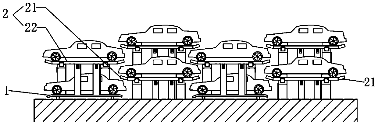
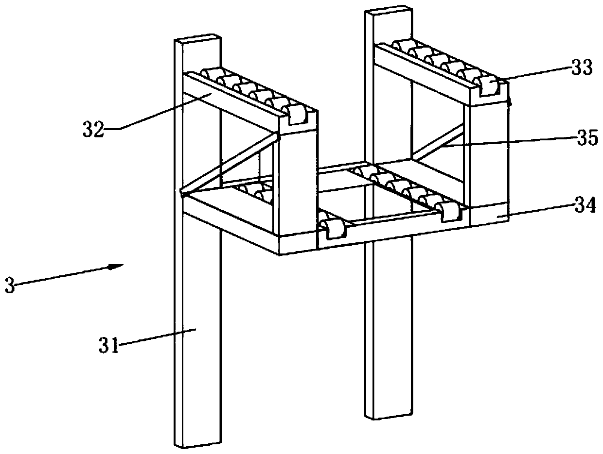
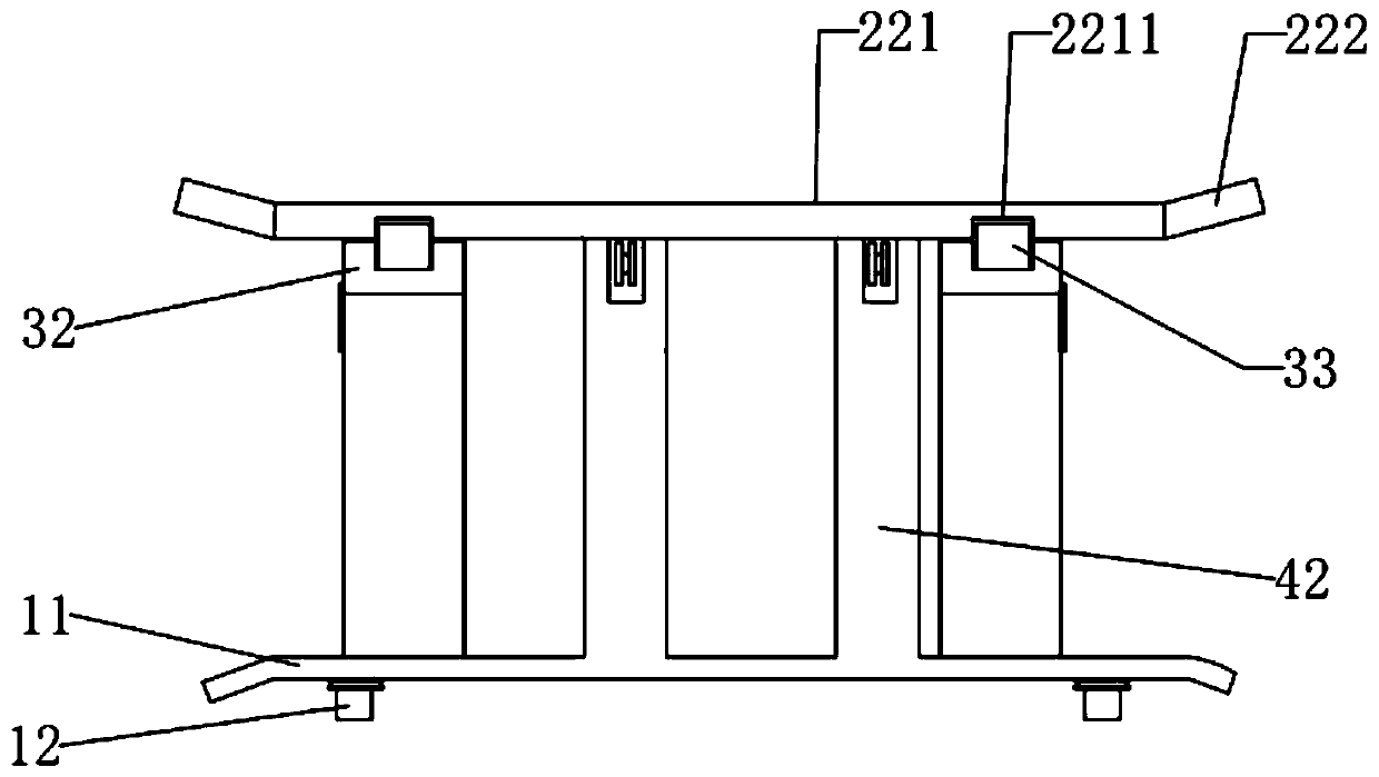
[0033] A staggered liftable multi-storey parking rack, such as Figure 1 to Figure 7 As shown, it includes a bottom frame 1 and a lifting frame 2 arranged on the upper side of the bottom frame 1. There are several bottom frames 1 horizontally spaced apart, and the lifting frame 2 includes two adjacent bottom frames. 1 the two-layer car board 21 above the middle position, and the three-layer car board 22 arranged above the middle position of two adjacent two-layer car boards 21; 21. The fixed bracket 3 supported by the three-layer vehicle board 22; a moving device for dragging the second-layer vehicle board 21 and the third-layer vehicle board 22 out of the fixed bracket 3 is provided on the side of the bottom vehicle frame 1 away from the fixed bracket 3 4. The moving device 4 is provided with a driving device 5 that drives the two-layer car board 21 and the third-layer car board 22 to move up and down. When in use, the two-layer car board 21 and the third-layer car board 22 ...

Embodiment 2

[0049] combine Figure 8 and Figure 9 As shown, the lifting assembly 52 includes an active screw rod 523 vertically rotatably arranged on the sliding joint column 51 and / or the moving column 42, an active support block 524 threaded on the active screw rod 523, and actively supported The block 524 is extended with an active support plate 525 near the side between the sliding joint post 51 and the moving column 42, and the lift parking plate 221 can abut on the active support plate 525; on the sliding joint post 51 and / or The moving column 42 is provided with a drive motor 526 that drives the active screw mandrel 523 to rotate; the sliding column 51 and / or the moving column 42 is provided with a first long groove 511, and the active support block 524 can be moved along the first long groove 511, Move straight down.

Embodiment 3

[0051] like Figure 10 As shown, the auxiliary support plate 34 is provided with an auxiliary roller 36, and the mounting plate 23 is arranged in parallel below the lifting parking plate 221. The side of the mounting plate 23 away from the lifting parking plate 221 is provided with an auxiliary long groove 231, and the auxiliary roller The wheel 36 is fitted in the auxiliary long groove 231; the lifting and moving assembly 6 that drives the lifting and parking plate 221 up and down is arranged on the mounting plate 23.

[0052] Lifting and moving assembly 6 comprises support rod 61, and one end of support rod 61 is hinged on the mounting plate 23, and the other end is provided with support roller 62, and support roller 62 abuts on the lower side of lifting parking plate 221, on the mounting plate 23 An oil cylinder 63 is provided, and the piston end of the oil cylinder 63 is rotatably connected to the support rod 61 ; a hook 43 is provided on the moving column 42 and on one si...


PUM


Abstract

The embodiment of the invention discloses a staggered liftable multi-layer parking rack, and relates to the technical field of parking racks. The staggered liftable multi-layer parking rack comprisesa bottom-layer vehicle frame and a lifting vehicle frame arranged on an upper side of the bottom-layer vehicle frame, wherein a plurality of bottom-layer vehicle frames are horizontally arranged at intervals; the lifting vehicle frame comprises two-layer vehicle boards arranged above two adjacent bottom-layer vehicle frames and three-layer vehicle boards arranged above two adjacent two-layers vehicle boards; a fixed bracket for supporting the two-layer vehicle boards and the three-layer vehicle boards is vertically and fixedly arranged on one side of the bottom-layer vehicle frame; a moving device for dragging the two-layer vehicle boards and the three-layer vehicle boards out of the fixed bracket is arranged on the one side of the bottom-layer frame far away from the fixed bracket; and adriving device for driving the two-layer vehicle boards and the three-layer vehicle boards to move up and down is arranged on the moving device. The staggered liftable multi-layer parking rack solvesthe problem that the prior art has less parking spaces and cannot meet needs of people.

Description

technical field [0001] The embodiment of the present invention relates to the technical field of parking racks, in particular to a staggered liftable multi-storey parking rack. Background technique [0002] At present, parking "difficult to find" has become a serious urban disease, which greatly affects the traffic order in the city, destroys the environment, and brings great inconvenience to people's life and work. In order to park vehicles, vehicles traveling back and forth in the city increase traffic congestion to a certain extent, consume too much resources and pollute the air, delay people's precious time, and reduce work efficiency. Contents of the invention [0003] Therefore, the embodiment of the present invention provides a staggered liftable multi-storey parking rack to solve the problem that there are few parking spaces in the prior art and cannot meet people's needs. [0004] In order to achieve the above purpose, embodiments of the present invention provide...

Claims


Application Information

Patent Timeline
Patent Type & Authority Applications(China)
IPC IPC(8): E04H6/18E04H6/20E04H6/24
Inventor 李剑峰
Owner 李剑峰
Why Eureka
Try Eureka