Two-way flow resistance testing system and method suitable for different fluid devices
A fluid equipment and testing system technology, which is applied in the testing of mechanical parts, liquid/fluid solids measurement, and testing of machine/structural parts, etc. The effect of large variation range, guaranteed measurement environment and fast response speed
- Summary
- Abstract
- Description
- Claims
- Application Information
AI Technical Summary
Problems solved by technology
Method used
Image

Examples
Embodiment 1
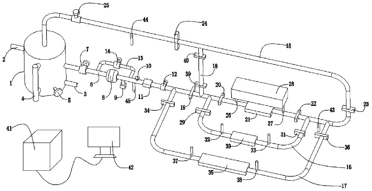
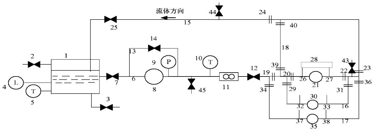
[0083] Embodiment one, with reference to the attached Figure 4As shown, when the fluid equipment to be tested needs to be installed in the first test pipe section 21, and the fluid equipment is a large fluid equipment, such as a large pump body, and the forward resistance characteristic measurement of the equipment is to be performed, the first pipeline is opened 6 on the first regulating valve 7, the second regulating valve 12, close the third regulating valve 14 on the second pipeline 13, open the first shut-off valve 19, the second shut-off valve 20, the second shut-off valve on the third pipeline 15 Three shut-off valves 22, the fourth shut-off valve 23, the fifth shut-off valve 24, the fourth regulating valve 25, simultaneously close the sixth shut-off valve 29 and the seventh shut-off valve 31 on the fourth pipeline 16, and close the fifth pipeline The eighth shut-off valve 34, the ninth shut-off valve 36 on 17, and the tenth shut-off valve 39 and the eleventh shut-off ...
Embodiment 2
[0084] Embodiment two, referring to the attached Figure 5 As shown, when it is necessary to install fluid equipment to be tested on the first test pipe section 21, and the fluid equipment is a large fluid equipment, such as a large pump body, and the reverse resistance characteristic measurement of the equipment is to be performed, the first pipeline is opened The first regulating valve 7 and the second regulating valve 12 on 6, close the third regulating valve 14 on the second pipeline 13, open the eighth shut-off valve 34 and the ninth shut-off valve 36 on the fifth pipeline 17, and pass The conduction blind plate makes the third test pipe section 35 in a conduction state, opens the second shut-off valve 20, the third shut-off valve 22, and the fourth regulating valve 25 on the third pipeline 15, and closes the first shut-off valve 19 and the fourth regulating valve at the same time. Four shut-off valves 23, close the sixth shut-off valve 29 and the seventh shut-off valve 3...
Embodiment 3
[0085] Embodiment three, with reference to the attached Image 6 As shown, when the fluid equipment to be tested needs to be installed in the second test pipe section 30, and the fluid equipment is a large fluid equipment, such as a large pump body, and the forward resistance characteristic measurement of the equipment is to be performed, the first pipeline is opened 6 on the first regulating valve 7, the second regulating valve 12, close the third regulating valve 14 on the second pipeline 13, open the first shut-off valve 19, the fourth shut-off valve 23, the third shut-off valve on the third pipeline 15 Five shut-off valves 24, fourth regulating valve 25, simultaneously close the second shut-off valve 20, the third shut-off valve 22, open the sixth shut-off valve 29 and the seventh shut-off valve 31 on the fourth pipeline 16, close the fifth pipeline The eighth shut-off valve 34 and the ninth shut-off valve 36 on 17, and close the tenth shut-off valve 39 and the eleventh sh...
PUM
 Abstract
Description
Claims
Application Information
 - Generate Ideas
- Intellectual Property
- Life Sciences
- Materials
- Tech Scout
- Unparalleled Data Quality
- Higher Quality Content
- 60% Fewer Hallucinations
Browse by: Latest US Patents, China's latest patents, Technical Efficacy Thesaurus, Application Domain, Technology Topic, Popular Technical Reports.
© 2025 PatSnap. All rights reserved.Legal|Privacy policy|Modern Slavery Act Transparency Statement|Sitemap|About US| Contact US: help@patsnap.com