Correction-free numerical control chamfering algorithm based on polar coordinate machine tool

A polar coordinate and chamfering technology, applied in the field of correction-free numerical control chamfering algorithm, can solve the problems of high customization cost, low efficiency of manual correction method, automatic centering tooling, etc.

Active Publication Date: 2019-06-28
NANJING GONGDA CNC TECH
View PDF11 Cites 1 Cited by
  • Summary
  • Abstract
  • Description
  • Claims
  • Application Information

AI Technical Summary

Problems solved by technology

[0004] The purpose of the present invention is to provide a correction-free numerical control chamfering algorithm based on a polar coordinate machine tool to solve the problem of the low efficiency of the manual

Method used


Image

  • Correction-free numerical control chamfering algorithm based on polar coordinate machine tool
  • Correction-free numerical control chamfering algorithm based on polar coordinate machine tool
  • Correction-free numerical control chamfering algorithm based on polar coordinate machine tool

Examples


Embodiment 1

[0036] The invention provides a correction-free numerical control chamfering algorithm based on a polar coordinate machine tool, comprising the following steps:

[0037] Step 1: Use a trigger probe to measure on two planes, and use the least square method to obtain the gear rotation center and axis position;

[0038] Step 2: Establish a mathematical model of the conversion relationship between the chamfering processing coordinate system and the workpiece coordinate system;

[0039] Step 3: Obtain the position of the upper end surface of the gear by collecting points, as a basis to determine the position of the chamfering target profile, and convert to the chamfering processing coordinate system;

[0040] Step 4: Obtain the intersection line between the gear chamfering target end plane and the chamfering tool;

[0041] Step 5: Calculate the tool position for chamfering according to the principle of space envelope.

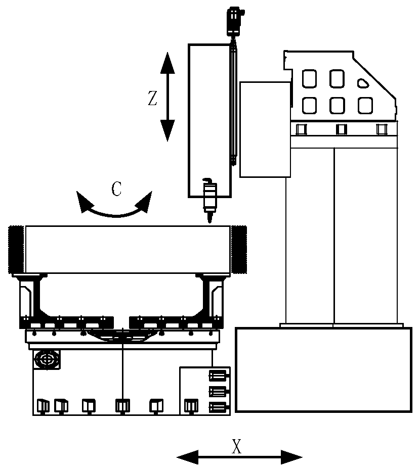
[0042] In this embodiment, the installation position of the ...

Embodiment 2

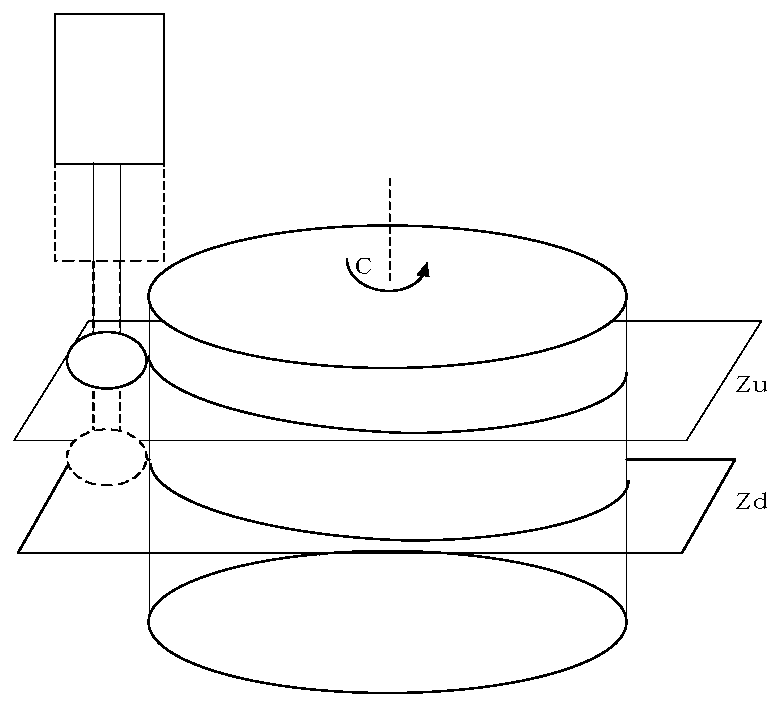
[0046] As the second embodiment of the present invention, in order to obtain the gear rotation center and axis position accurately, the inventors improved the method of step 1. As a preferred embodiment, the gear rotation center and axis position are obtained in step 1 The specific method is as follows:

[0047] S1-1. Use a trigger probe concentric with the chamfering tool, take the upper and lower Z value planes Zu and Zd, rotate the C axis to measure the outer circle of the gear, and get 5 data points for each plane, namely (ρ u1 , θ u1 ), (ρ u2 , θ u2 )……, (ρ u5 , θ u5 ), (ρ d1 , θ d1 )(ρ d2 , θ d2 )……, (ρ d5 , θ d5 );

[0048] S1-2. Convert the measured points into the three-dimensional Cartesian coordinate system SO(O-X, Y, Z), where the Z axis coincides with the rotary axis of the turntable, and the X axis coincides with the X axis of the machine tool, so that (x u1 ,y u1 ,z u1 ),..., (x u5 ,y u5 ,z u5 ), (x d1 ,y d1 ,z d1 ),..., (x d5 ,y d5 ,z d5 ...

Embodiment 3

[0065] As the second embodiment of the present invention, in order to facilitate the conversion between the chamfering processing coordinate system and the workpiece coordinate system, the inventors improved the method of step 2. As a preferred embodiment, the chamfering processing coordinate system is established in step 2 The specific method of the mathematical model of the conversion relationship with the workpiece coordinate system is as follows:

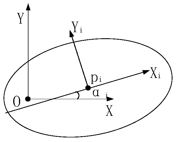
[0066] S2-1. Let the center point of any Z plane gear be Pi(x i ,y i ,z i );

[0067] S2-2. Establish a coordinate system SP(Pi-Xp, Yp, Zp);

[0068] S2-3, coincide the direction of the Zp axis in the coordinate system SP established in step S2-2 with the vector v.

[0069] In this example, if Figure 4 As shown, the transformation relationship formula of the coordinate system SO and SP is as follows:

[0070]

[0071]

[0072] Mpo=Rpo*Tpo

[0073] Mop = Mpo -1

[0074] in,

[0075]

[0076]


PUM


Abstract

The invention relates to the technical field of numerical control machinery, in particular to a correction-free numerical control chamfering algorithm based on a polar coordinate machine tool. On thebasis of a machining principle of the polar coordinate machine tool which only has an X axis, a Z axis and a C axis, a cylindrical gear is free of correction, eccentric deflection is detected automatically, under the state, a deflection axis does not need to be added, and space chamfering is realized by a cone curve on a cone cutter. According to the method, any two measurable planes in the axialdirection are selected, points are respectively collected according to an equal angle method, relative position models of a machining coordinate system and a workpiece coordinate system are established, a mutual conversion relation is obtained, the position of a target machining contour of the cylindrical gear in the machining coordinate system is obtained, and a cutter point is obtained accordingto the cutting characteristic of the cone curve. The chamfering processing operation process is simplified, and the processing efficiency is improved.

Description

technical field [0001] The invention relates to the technical field of numerical control machinery, in particular to a correction-free numerical control chamfering algorithm based on a polar coordinate machine tool. Background technique [0002] CNC chamfering of gears is an auxiliary process before heat treatment of gears. The efficiency of manual chamfering is low, and the chamfering effect depends on the skills of workers, which is difficult to control. CNC chamfering can improve the quality of gear chamfering and ensure the effect of heat treatment. [0003] In order to meet the processing quality requirements, the end runout and radial runout of cylindrical gears must be corrected before chamfering. At present, the calibration of domestic enterprises generally adopts the method of manual calibration or automatic centering tooling. The efficiency of the manual correction method is low; the automatic centering tooling is generally suitable for small-sized gears, and th...

Claims


Application Information

Patent Timeline
IPC IPC(8): G05B19/19
Inventor 孙小敏洪荣晶于春建崔君君
Owner NANJING GONGDA CNC TECH
Why Eureka
Try Eureka