
A hydraulic-electric hybrid slip ring device

A slip ring device, liquid gas technology, applied in the direction of electrical components, circuits, current collectors, etc., can solve the problems of conductive copper ring wear, unstable rotor sealing performance and torque performance, low pressure, etc., to achieve enhanced sealing performance and torque , Ensure long-term stable work and improve service life

Inactive Publication Date: 2020-05-15
张祝 +1
View PDF5 Cites 0 Cited by
  • Summary
  • Abstract
  • Description
  • Claims
  • Application Information

AI Technical Summary

Problems solved by technology

[0002] The currently used hybrid slip rings have unstable rotor sealing performance and torque performance, and are prone to leakage. When high current is supplied, the heat dissipation effect is poor, which seriously affects the stability of the slip ring operation.
In order to solve the problem of rotating and transferring the rotor between dynamic and static, the electric drive part and the liquid-pneumatic drive part are integrated together. However, this design has problems such as inconvenient winding of the equipment, and the rotor cannot simultaneously realize the transmission of liquid-pneumatic power when rotating. ; At the same time, the contact between the fiber brush and the conductive copper ring in the hybrid slip ring currently used is inconsistent, and the conductive copper ring is severely worn under high pressure, and the service life is damaged; the pressure is too small, the contact is not complete, and the signal is easy to lose

Method used


Image

  • A hydraulic-electric hybrid slip ring device
  • A hydraulic-electric hybrid slip ring device
  • A hydraulic-electric hybrid slip ring device

Examples


Embodiment Construction

[0034] In order to make the technical means, creative features, goals and effects achieved by the present invention easy to understand, the present invention will be further described below in conjunction with specific illustrations.

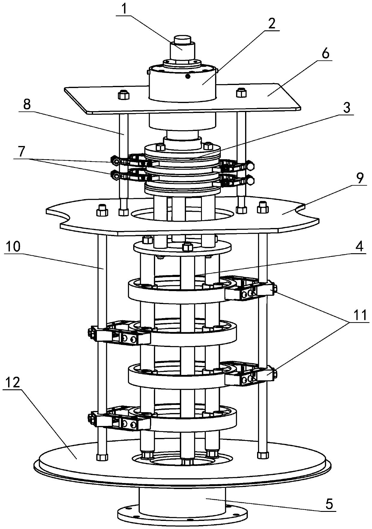
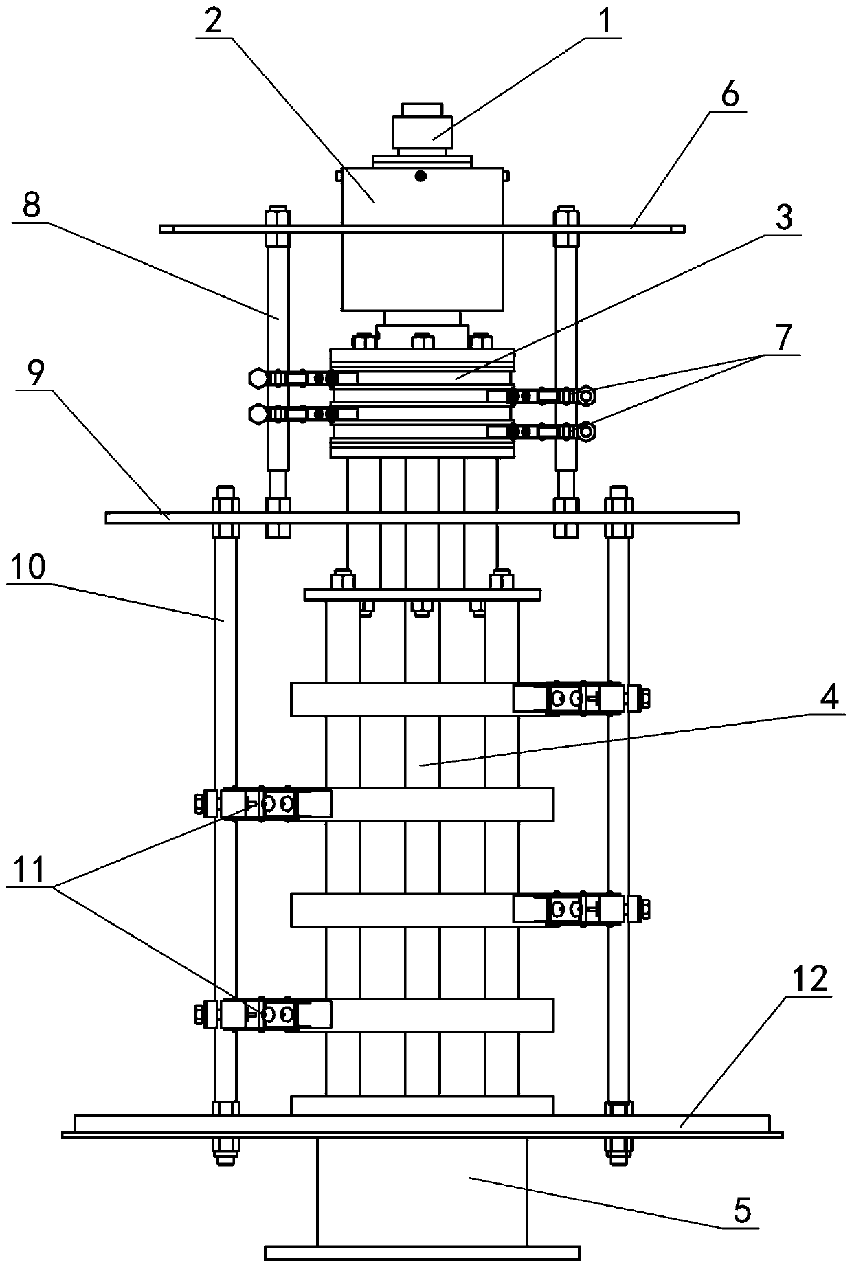
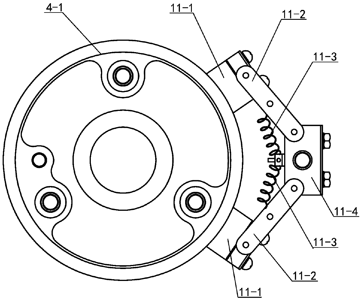
[0035] see Figure 1 to Figure 11 A liquid-electric hybrid slip ring device, including a rotor and a stator, and the rotor is installed on the stator, and the rotor is composed of a liquid-gas control part 1, a slip ring signal part 2, a conductive power part 3, a conductive high-current part 4, and a rotor flange Composed of 5, the stator is composed of an upper support plate 6 of the brush rod, a small contact brush 7, a small insulating and fixed rod 8, a lower support plate of the brush rod 9, a large insulating and fixed rod 10, a large contact brush 11 and a stator bottom plate 12, wherein, The rotor flange 5 is connected with the conductive high current part 4, the conductive high current part 4 is set on the conductive power part 3, the ...


PUM


Abstract

Provided is a liquid, power and gas mixed slip ring device. A conductive heave-current part of a rotor is internally provided with multiple heavy-current conductive copper rings, when power and heavycurrent are provided, the heavy-current conductive copper rings make contact with a heavy-current support tube to make transmission, and a heat radiation structure of the conductive heave-current partis optimized effectively; a through hole through which a rotor wire can pass is arranged in a mandrel of a slip ring, problems as wiring in the device can be solved effectively; wires of a stator part can be output via the side surface, bottom or top, and connected with a static device to solve problems in moving and static rotary switching; a liquid and gas control part and a slip ring signal part are provided with casings respectively to enhance the sealing performance and torsional force of the device, gas leakage is prevented, and integrated liquid, power and gas transmission is realized;and small contact brushes make contact with power copper rings, large contact brushes make contact with the heavy current conductive copper rings, pressure contact between the brushes and the copperrings is controlled to reduce wearing of the copper rings, prolong the service life of the copper rings, and further provide stable signals.

Description

technical field [0001] The invention relates to the technical field of automation equipment, in particular to a hydraulic-electric hybrid slip ring device. Background technique [0002] The currently used hybrid slip rings have unstable rotor sealing performance and torque performance, and are prone to leakage. When a large current is supplied, the heat dissipation effect is poor, which seriously affects the stability of the slip ring. In order to solve the problem of rotating and transferring the rotor between dynamic and static, the electric drive part and the liquid-pneumatic drive part are integrated together. However, this design has problems such as inconvenient winding of the equipment, and the rotor cannot simultaneously realize the transmission of liquid-pneumatic power when rotating. ; At the same time, the contact between the fiber brush and the conductive copper ring in the hybrid slip ring currently used is inconsistent, the conductive copper ring is severely wo...

Claims


Application Information

Patent Timeline
Patent Type & Authority Patents(China)
IPC IPC(8): H01R39/08F16L39/06F16L25/01
Inventor 张祝
Owner 张祝
Learn More