Pole-climbing robot

A robot and pole-climbing technology, which is applied in the field of pole-climbing robots, can solve problems such as potential safety hazards, inability to use for a long time, robot falling, etc., and achieve the effect of simple and convenient adjustment process, safe and reliable power consumption

Active Publication Date: 2019-07-02
临颍县爬杆机器人有限公司
View PDF4 Cites 10 Cited by
  • Summary
  • Abstract
  • Description
  • Claims
  • Application Information

AI Technical Summary

Problems solved by technology

However, this kind of robot also has the following problems: first, if the electric worker stands on the robot, the overturning moment of the counterweight may be offset, causing the robot to release the self-lock and fall, which has potential safety hazards; secondly, due to the increase Due to the counterweight and self-locking, the driving force required to drive the motor is relatively large, resulting in a severe energy consumption of the battery, and it cannot be used for a long time

Method used


Image

  • Pole-climbing robot
  • Pole-climbing robot
  • Pole-climbing robot

Examples


Embodiment 2

[0048] Embodiment 2: The arrangement of the upper and lower rows of the traveling wheel mechanism in this embodiment, each row having two rubber-coated wheels arranged at intervals, is the same as that of the traveling wheel mechanism in Embodiment 1, the difference is that: The structural form of the frame, the structure and arrangement of the telescopic mechanism, and the structure and arrangement of other auxiliary components are all different, and may be common forms in the prior art.

Embodiment 3

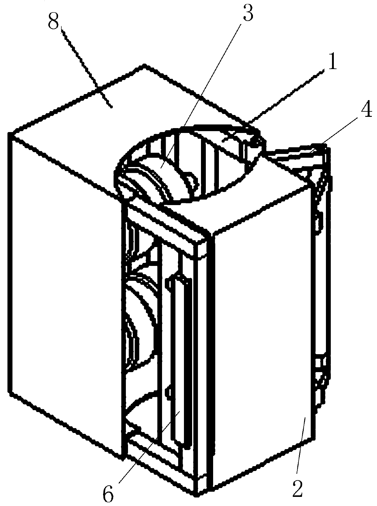
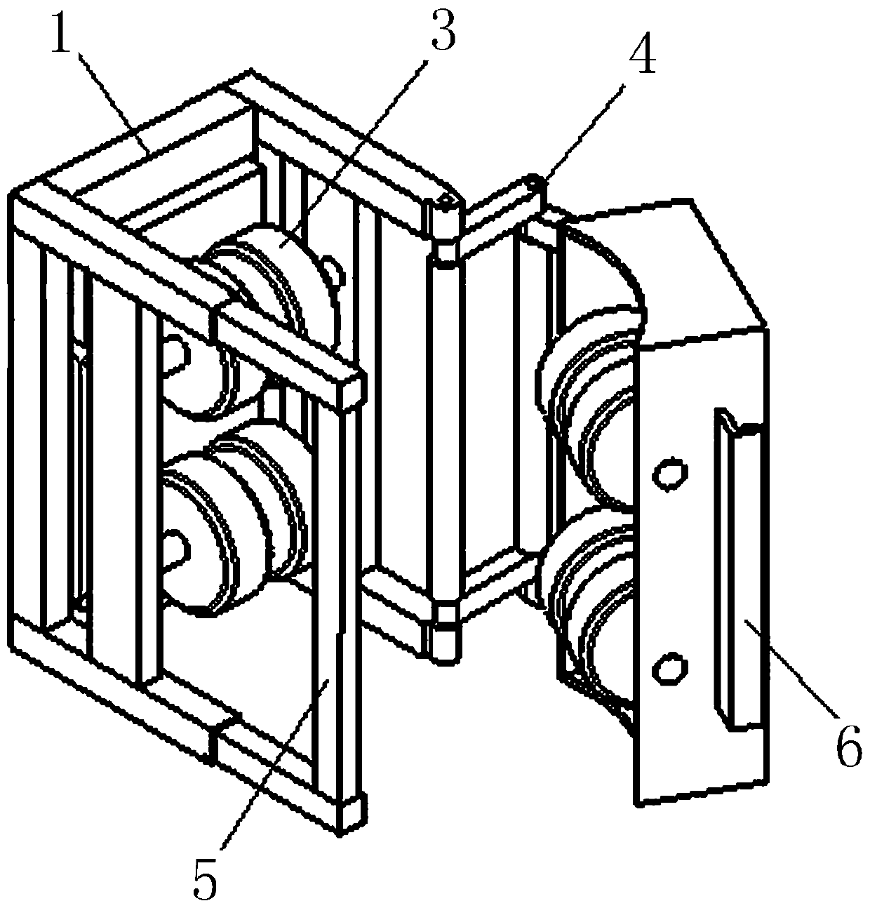
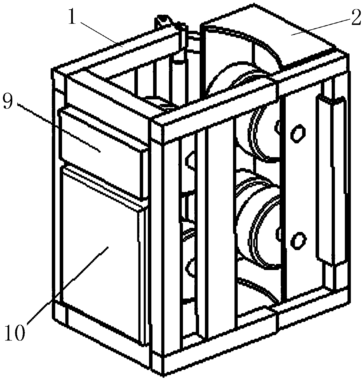
[0049] Embodiment 3: as Figure 6-8 As shown, the difference from Embodiment 1 is that both sides of the structure of the two frames are provided with telescopic mechanisms, and one end of the telescopic mechanism on one side is rigidly connected to the second frame, and the other end is passed through the hinge 30 (ie, the hinge). Flexible connection with the first frame; one end of the telescopic mechanism on the other side is rigidly connected with the first frame, and the other end is connected with the buckle structure of the second frame through an openable buckle structure, that is, U-shaped movable hook 5 and fixed hook 6 , the two telescopic mechanisms are respectively rigidly connected with the first frame and the second frame to form an L-shaped frame, and the two L-shaped frames face each other to form a rectangular frame, and a joint of the two L-shaped frames is connected by the hinge 30 The other connection is a detachable connection formed by the movable hook 5...

Embodiment 4

[0050] Embodiment 4: as Figure 9-11 As shown, the difference from Embodiment 3 is that one side of the two frames is respectively rigidly connected to the two ends of a telescopic rod 31 to form a C-shaped frame, and then a hinge 30 is hinged at the opening of the C-shaped frame. Telescopic rod 31, the other end of telescopic rod 31 realizes detachable connection through the hooking cooperation of T-shaped movable hook 5 and fixed hook 6 with a gap for T-shaped hook to hang in the middle on the C-shaped frame. 31 forms an I-shaped structure, and the C-shaped structure and the I-shaped structure are assembled into a rectangular structure, and the approach and separation between the walking wheel mechanisms are realized through the expansion and contraction of the two telescopic rods 31. This embodiment is a C+I-shaped structure. Of course, the T-shaped movable hook 5 in this embodiment can also be replaced by a rectangular hook or a 7-shaped hook.

[0051] In other embodiment...


PUM


Abstract

The invention relates to a pole-climbing robot. The pole-climbing robot comprises a first frame body and a second frame body. Walking wheel mechanisms are arranged on the first frame body and the second frame body. The two sides of the walking wheel mechanism of one of the two frame bodies is correspondingly connected with the two sides of the other walking wheel mechanism of the other walking wheel mechanism through two connecting structures respectively. In this way, the walking wheel mechanisms on the two frame bodies are oppositely arranged. An accommodating space for a pole-climbing bodyto penetrate through is formed between the two walking wheel mechanisms. One of the two connecting structures is a flexible connecting structure, and the other connecting structure is a detachable connecting structure. At least one of the side edges of the two sides of the walking wheel mechanisms of the two frame bodies is provided with an active contraction mechanism for adjusting the length ofthe side edge. When the length of one side is adjusted through the active contraction mechanism, the contraction deformation amount can be compensated through the arrangement of the flexible connection structure. The whole adjusting process is simple, convenient, safe and reliable. The power consumption is low in the crawling process, and the pole-climbing robot is very practical.

Description

technical field [0001] The invention relates to a pole climbing robot. Background technique [0002] With the development of electric power and network, the erection and maintenance of wires and cables is the most important thing to ensure the smooth transmission of power and network. But for the beauty and smoothness of the city, most of the wire and cable facilities are erected on quite high poles, which are usually 4.5 to 15 meters high. Electric workers need to carry out relevant operations on the upper part of the utility pole. The traditional way is to use large-scale engineering vehicles to operate, or the electric workers need to climb up to operate, and sometimes need to transport wires and cables upwards. Electric workers generally Climbing through the foot buckle, and the use of the foot buckle method is not only poor in safety and very inconvenient to operate, but also more inconvenient when the foot buckle is operated to transport objects on the rod body. [0...

Claims


Application Information

Patent Timeline
Patent Type & Authority Applications(China)
IPC IPC(8): B62D57/024
CPCB62D57/024
Inventor 贾针贾德增
Owner 临颍县爬杆机器人有限公司
Why Eureka
Try Eureka