Two-stage cavitation generator with composite structure

A composite structure and generator technology, applied in the field of cavitation generators, can solve problems such as failure to restore the initial pressure value in time, failure to ensure smooth completion, failure to ensure cavitation effects, etc., to achieve strong cavitation effects, compact structure, Material saving effect

Pending Publication Date: 2019-07-02
JIANGSU UNIV OF SCI & TECH
View PDF7 Cites 8 Cited by
  • Summary
  • Abstract
  • Description
  • Claims
  • Application Information

AI Technical Summary

Problems solved by technology

[0003] After literature search, it was found that the Chinese invention patent with the patent publication number "CN107930548A" discloses "a cavitation generator capable of realizing two-stage cavitation", which combines an orifice plate and a Venturi tube into one tube, but the The cavitation process of the orifice plate and the Venturi tube of the cavitation generator is independent and separate. Whether cavitation can occur in the orifice plate cavitation generator is related to many factors, such as the opening ratio, hole diameter, and hole size. Arrangement methods, etc., and there are some optimal parameter values, but this invention only provides a simple model diagram, and does not provide the specific parameter range and the relationship between the parameter values ​​​​at the best cavitation effect, so The first-stage cavitation process of the cavitation generator cannot be guaranteed to be completed smoothly, nor can it be guaranteed to achieve the best cavitation effect; on the other hand, because the function of the orifice plate is to throttle and reduce pressure, when the water flow After the cavitation process is completed, the initial pressure value cannot be restored in time, and the pressure of the water flow entering the Venturi tube is lower than the initial pressure value. According to the data, the occurrence of cavitation is closely related to the pressure, and the pressure value at the inlet of the cavitation generator is higher. The higher the cavitation effect of the cavitation generator, the better

Method used


Image

  • Two-stage cavitation generator with composite structure
  • Two-stage cavitation generator with composite structure
  • Two-stage cavitation generator with composite structure

Examples


Embodiment

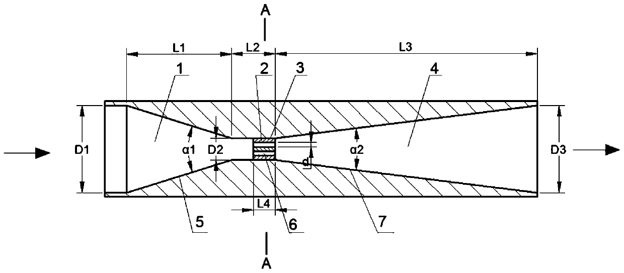
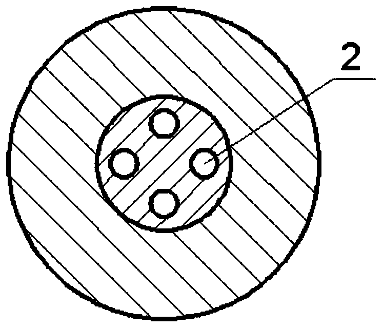
[0025] like Figure 1-Figure 2 As shown, it is a two-stage cavitation generator of a composite structure of the present invention, including a Venturi tube and an orifice plate 2, wherein the Venturi tube has a tubular appearance, and consists of an inlet end 1, a tapered section 5, a throat Section 3 , expanding section 7 , outlet end 4 , the orifice plate 2 is provided with a number of holes 6 , which are arranged in the throat section 3 .

[0026] The tapered section 5 is a frustum-shaped inner hole, and its central angle α 1 is 30°~50°; the expanding section 7 is a frustum-shaped inner hole, and its central angle α 2 It is 18°~30°.

[0027] The inlet end 1 is a round pipe with equal inner diameter connected to the tapered section 5 , and the outlet end 4 coincides with the divergent section 7 .

[0028] The diameter of the orifice plate 2 is equal to the section diameter of the throat section 3, and the relational expression between the quantity of the holes 6 and the d...


PUM


Abstract

The invention discloses a two-stage cavitation generator with a composite structure. The two-stage cavitation generator comprises a Venturi tube and an orifice plate. The exterior of the Venturi tubeis tubular, and the Venturi tube is successively composed of an inlet end, a gradual contraction section, a throat section, a gradual enlargement section and an outlet end. The orifice plate is provided with several pore channels, which are arranged in the throat section. The two-stage cavitation generator is an integrated two-stage cavitation generator with the orifice plate and the Venturi tubenested. Through simulation verification, the two-stage cavitation generator can complete two cavitation processes when boundary conditions are certain, has higher cavitation efficiency than a traditional single-stage cavitation generator, and has a better cavitation effect and larger cavitation area to release more energy in comparison with a combined cavitation generator formed by direct connection of an orifice plate and a Venturi tube. By combining advantages of a traditional single-stage cavitation generator and optimizing the structure of the combined cavitation generator, the optimum structure value relation is brought forward. The two-stage cavitation generator has engineering development value and anapplication prospect.

Description

technical field [0001] The invention relates to a cavitation generator, in particular to a cavitation generator with a composite structure that can realize two-stage cavitation effects. The cavitation generator has a wide range of applications and can be used for sewage treatment, seawater desalination, and dirt cleaning , wherein it can also be used as a heat source, and form a system device that utilizes the cavitation mechanism to enhance liquid convective heat exchange with a heat exchange device. Background technique [0002] Cavitation mechanism: Cavitation refers to the process of formation, development and collapse of vapor or gas cavities (cavitations) inside the liquid or on the liquid-solid interface when the local pressure in the liquid decreases. Existing studies have shown that the rapid collapse of cavitation bubbles will generate local high temperature and high pressure in a very small area around them, forming so-called "hot spots", accompanied by strong sho...

Claims


Application Information

Patent Timeline
Patent Type & Authority Applications(China)
IPC IPC(8): C02F1/34
CPCC02F1/34
Inventor 杨兴林石园园程林闫利坤何芳黄川唐杰
Owner JIANGSU UNIV OF SCI & TECH
Why Eureka
Try Eureka