Method for dividing dynamic flowing units of extra-high-water-cut stage oil reservoir

A technology of ultra-high water cut period and flow unit, which is applied in the fields of production fluid, earthwork drilling and production, and special data processing applications, etc. It can solve problems such as inability to describe and solve invalid drives, and no combination of geology and reservoirs.

Active Publication Date: 2019-07-02
CHINA UNIV OF PETROLEUM (EAST CHINA) +1
View PDF3 Cites 8 Cited by
  • Summary
  • Abstract
  • Description
  • Claims
  • Application Information

AI Technical Summary

Problems solved by technology

A flow unit is defined as a reservoir that is continuously distributed in space and has similar petrophysical and seepage characteristics. The study of a flow unit is of great practical significance for analyzing the distribution of oil and water in the ground and predicting the distribution of remaining oil. However, as a geological Quantitative means of volume description, the existing flow unit division method does not well combine geology and reservoir, and cannot describe and solve the problem of ineffective driving in the later stage of development, and provide a basis for oilfield development adjustment

Method used


Image

  • Method for dividing dynamic flowing units of extra-high-water-cut stage oil reservoir
  • Method for dividing dynamic flowing units of extra-high-water-cut stage oil reservoir
  • Method for dividing dynamic flowing units of extra-high-water-cut stage oil reservoir

Examples


Embodiment Construction

[0040] In order to further describe the present invention, examples are used for detailed description.

[0041] Considering the heterogeneity of the reservoir, a five-point numerical simulation model is established according to the required conditions, and the flow units are divided for the ultra-high water-cut period. The model parameters are set as follows:

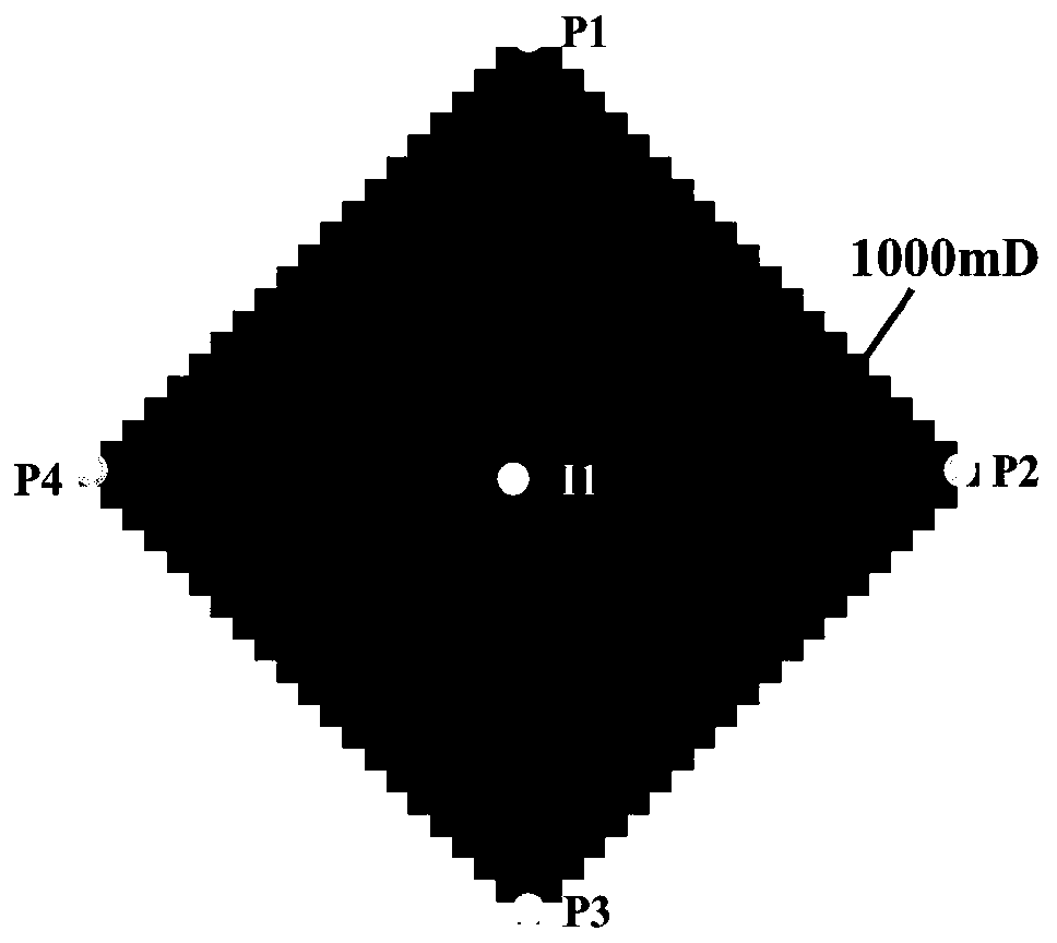
[0042] The distance between injection and production wells in the model is 300m; the model has a high permeability zone with a permeability of 1000mD, and the permeability on both sides of the high permeability zone is 500mD; the permeability at the boundary is low, the lowest is 50mD, and the permeability gradually changes to both sides; The injection wells (P1, P2, P3, P4) are distributed around the model, and the production well (I1) is in the center of the model. The schematic diagram of the model is as figure 1 shown.

[0043] Step 1: Regression and arrangement of 100 relative permeability curves in Shengli Oilf...


PUM


Abstract

The invention relates to a method for realizing dynamic flowing unit division of a floodable development reservoir in an extra-high-water-cut stage. The method comprises the following steps of step (1) according to the existing relative permeability curve of an oil field, performing regression to obtain a relative permeability curve expression under the condition of different absolute permeabilities; and further performing calculation to obtain the water phase relative permeability of each mesh point; step (2) calculating a water phase seepage flow coefficient: performing calculation to obtainthe water phase seepage flow coefficient of each mesh point in a model by using the water phase relative permeability of each mesh point obtained in the step (1) according to the definition of the seepage flow coefficient; step (3) determining a division limit; drawing a water phase water phase seepage flow coefficient semi-log accumulation curve graph; finding two parallel sections (with small slopes which are almost zero) and one section with the larger slope in the two parallel sections to be used as the division limit of the dynamic flowing units; and step (4) judging the affiliated region of the mesh; on the basis of the division limit in the step (3), performing region judgment on the water phase seepage flow coefficient of each mesh; and further dividing the flowing units.

Description

technical field [0001] The invention relates to the technical field of comprehensive adjustment of reservoirs for water injection development, in particular to a method for dividing flow units based on reservoir dynamic parameters after analyzing geological parameters after the reservoir enters an ultra-high water-cut period. Background technique [0002] At present, most oilfields in eastern my country have entered the stage of high water cut and ultra-high water cut. Under the situation that it is more and more difficult to find new reserve reserves and the reserve-production ratio is seriously out of balance, the development of remaining oil in old oilfields has become the sustainable development of old oilfields in eastern my country. major strategy. Revealing the quantity and distribution of remaining oil is an important basis for designing and optimizing water flooding development schemes and tertiary oil recovery schemes, while the quantity and spatial distribution of ...

Claims


Application Information

Patent Timeline
Patent Type & Authority Applications(China)
IPC IPC(8): E21B43/20E21B49/00G06F17/50G06F17/10
CPCE21B43/20E21B49/00G06F17/10G06F30/20
Inventor 崔传智杨勇孙业恒杜玉山刘志宏黄迎松隋迎飞唐从见郭长春
Owner CHINA UNIV OF PETROLEUM (EAST CHINA)
Why Eureka
Try Eureka