Undervoltage detection circuit applicable to low voltage environment

An under-voltage detection and low-voltage technology, applied in the direction of measuring current/voltage, measuring device, measuring electrical variables, etc., can solve the problems of reference reference voltage and comparator working status, which are difficult to guarantee, not applicable, and increase the resistance area.

Pending Publication Date: 2019-07-02
南京芯耐特半导体有限公司
View PDF0 Cites 2 Cited by
  • Summary
  • Abstract
  • Description
  • Claims
  • Application Information

AI Technical Summary

Problems solved by technology

[0003] The resistance and comparator of the commonly used power-off detection circuit structure consume DC power consumption during normal operation. Increasing the resistance can reduce the static power consumption of the resistance voltage divider, but it also inevitably increases the res

Method used


Image

  • Undervoltage detection circuit applicable to low voltage environment
  • Undervoltage detection circuit applicable to low voltage environment
  • Undervoltage detection circuit applicable to low voltage environment

Examples


Example Embodiment

[0021] The content of the present invention will be further described below in conjunction with the accompanying drawings of the specification. Obviously, the described embodiments are only a part of the embodiments of the present invention, rather than all the embodiments.

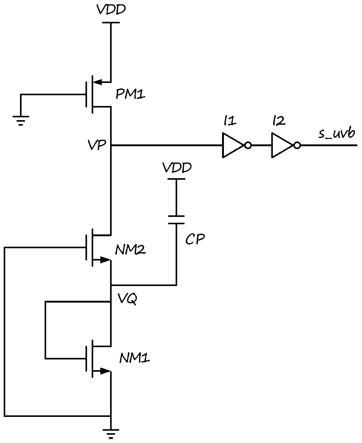
[0022] Such as figure 2 As shown, this embodiment provides an undervoltage detection circuit that can be applied to a low-voltage environment, including a PMOS tube PM1; NMOS tubes NM1 and NM2; inverters I1 and I2; a capacitor CP and a power supply voltage VDD.

[0023] PM1, connect to power supply voltage VDD, output voltage VP;

[0024] NM2, input voltage VP;

[0025] NM1, NM2, output voltage VQ;

[0026] CP, one end is connected to the power supply voltage VDD, the other end is connected in series with NM1 and NM2 respectively;

[0027] Two-stage inverter, formed by connecting I1 and I2 in series, input voltage VP signal, output undervoltage control signal;

[0028] PM1 is connected in series with NM2 and two-st...


PUM


Abstract

The invention provides an undervoltage detection circuit applicable to a low voltage environment, which comprises a PMOS transistor PM1, NMOS transistors NM1 and NM2, inverters I1 and I2, a capacitorCP and power supply voltage VDD, wherein one end of the capacitor CP is connected with the power supply voltage VDD and the other end is connected with the source end of the NM2; and the NM2 is a low-threshold NMOS transistor. The circuit provided in the invention can be applied in a low voltage environment and has no static power consumption under a normal operating condition.

Description

technical field [0001] The invention belongs to the field of integrated circuit design, and in particular relates to an undervoltage detection circuit applicable to a low voltage environment. Background technique [0002] Such as figure 1 As shown, in the commonly used power-off and undervoltage detection circuit structure, three series resistors are used to generate a divided voltage. The positive input terminal of the comparator is connected to a voltage division point, and the negative input terminal is connected to the reference reference voltage. After being shaped by the inverter, an undervoltage detection signal is generated, and it is valid when it is low. At the same time, the signal terminal is connected to the gate of the NMOS transistor, and the drain of the NMOS transistor is connected to the second voltage dividing point of the voltage dividing resistor. The source end of the NMOS transistor and one end of the third resistor are commonly grounded. When the d...

Claims


Application Information

Patent Timeline
IPC IPC(8): G01R19/165
CPCG01R19/16519
Inventor 庄在龙
Owner 南京芯耐特半导体有限公司
Why Eureka
Try Eureka