
Thread milling cutter

A thread milling cutter and thread tooth technology, applied in milling cutters, thread cutting tools, milling machine equipment, etc., can solve the problems of skewed central axis of thread milling cutters and short tool life of thread milling cutters, and achieve the effect of prolonging tool life.

Active Publication Date: 2019-07-02
OSG
View PDF7 Cites 0 Cited by
  • Summary
  • Abstract
  • Description
  • Claims
  • Application Information

AI Technical Summary

Problems solved by technology

[0008] However, in Patent Document 1, there is a problem that the thread milling cutter tends to be skewed with respect to the central axis of the internal thread due to the radial force received from the workpiece, resulting in a short tool life of the thread milling cutter.

Method used


Image

  • Thread milling cutter
  • Thread milling cutter
  • Thread milling cutter

Examples


Embodiment

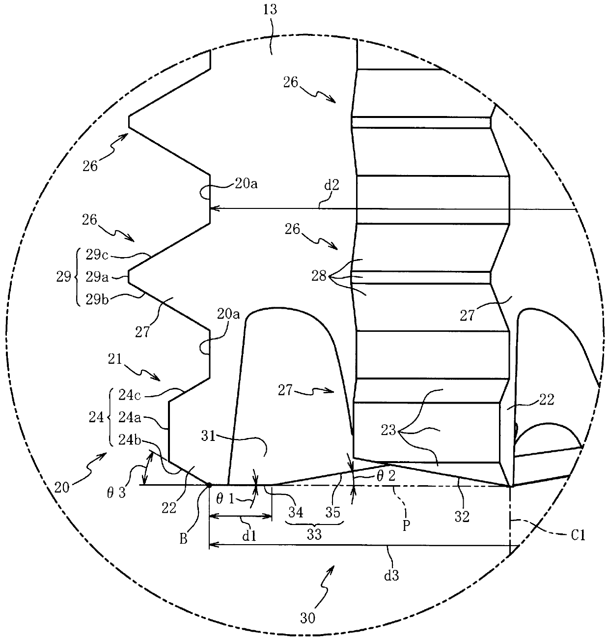
[0063] Hereinafter, the present invention will be described more specifically by way of examples. It should be noted that the present invention is not limited to the following examples. In the following examples, values ​​embodying the values ​​of the width d1 and the angle θ1 of the thread milling cutter 1 described in the above embodiment are used. In all the examples and comparative examples, the angle θ2 was set to 10°, and the angle θ3 was set to 30°.

[0064]First, Example 1 having the first bottom edge 34 and a comparative example not having the first bottom edge 34 are compared. Used in Example 1 and made: the angle θ1 is 0°~+1°, the width d1 is 0.19mm, and the root diameter d2 is 3.17mm, that is, the ratio d1 / d2 of the width d1 to the root diameter d2 is 6%. (error ±0.4%) thread milling cutter. It should be noted that "+" in the angle θ1 indicates that the first bottom edge 34 is inclined toward the rear end side as it moves toward the axis C1 side. In addition, t...

Embodiment 7

[0075] Embodiment 7 has the same configuration as Embodiment 6 except that the angle θ1 is made to be 1° to 2°. Embodiment 8 has the same configuration as Embodiment 6 except that the angle θ1 is made to be 3° to 4°. Embodiment 9 has the same configuration as Embodiment 6 except that the angle θ1 is made to be 5° to 6°.


PUM


Abstract

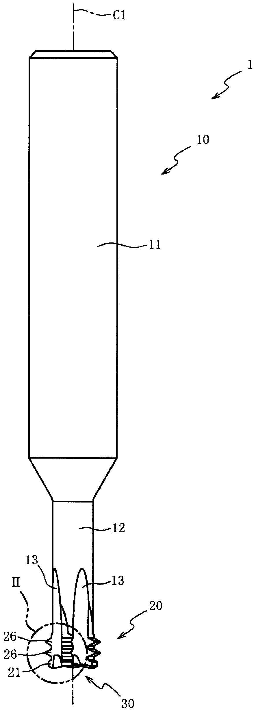
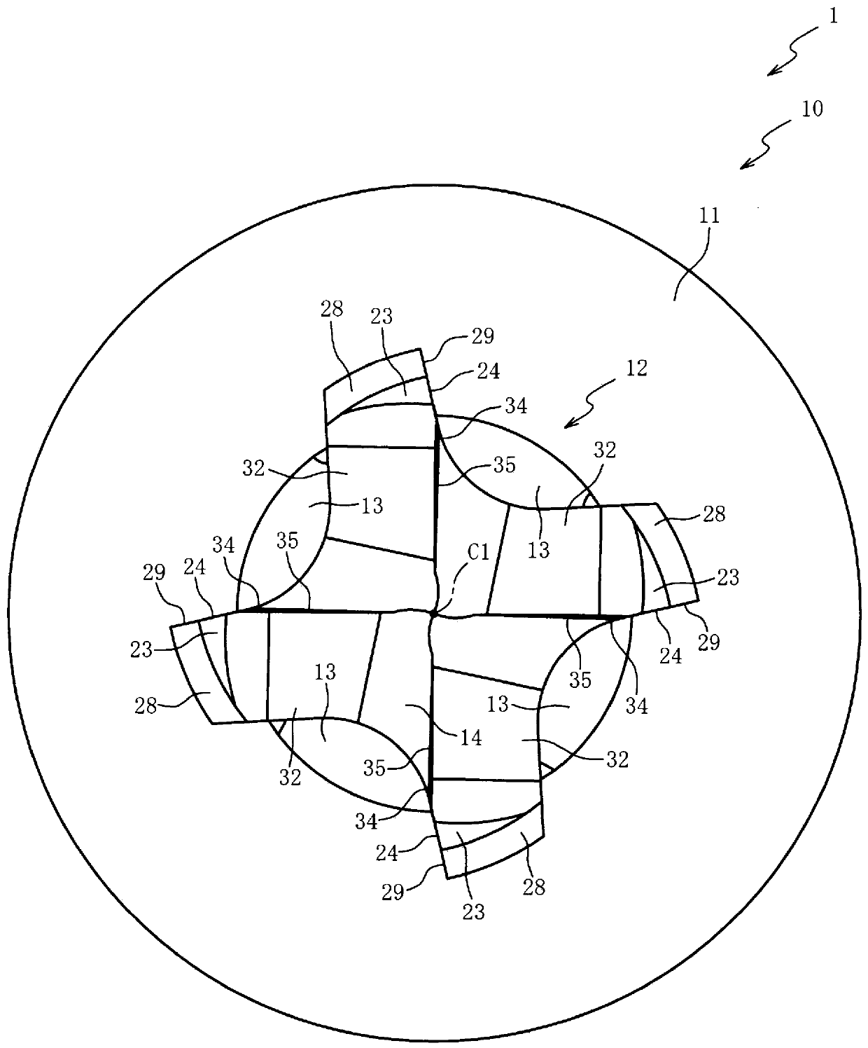
Provided is a thread milling cutter with which tool service life can be extended. Multiple thread ridges protrude from the leading end of the circumference of a tool body (10) in directions normal tothe axis to form thread milling edges (20a, 24, 29). The end cutting edges (33) formed on the leading end face of the tool body have a first end cutting edge (34), which is continuous with the leadingend of a thread milling edge, and a second end cutting edge (35), which is continuous with the shaft center (C)-end of the first end cutting edge and is sloped towards the back end compared to the first end cutting edge. The angle (Theta1) formed by an imaginary plane (P), which is perpendicular to the shaft center, and the first end cutting edge is set to be 6DEG or less. The angle ((Theta2) formed by the second end cutting edge and an imaginary plane (P), which is perpendicular to the shaft center, is set to be greater than the angle formed by the first end cutting edge and the imaginary plane perpendicular to the shaft center.

Description

technical field [0001] The present invention relates to a thread milling cutter, in particular to a thread milling cutter which simultaneously performs hole drilling and thread cutting. Background technique [0002] Conventionally, thread milling cutters have been known as tools for cutting internal threads on workpieces. In this thread milling cutter, a thread cutting edge is provided on the outer periphery of a tool body, and thread cutting is performed while rotating around an axis and moving relative to a workpiece by a driving device such as an NC milling machine. [0003] Among thread milling cutters, there is a kind of milling cutter that provides a bottom edge on the front end of the tool body, so that pre-drilling with other tools is not required as a pre-process of thread cutting, but hole drilling and thread cutting are performed simultaneously. (Patent Document 1). [0004] prior art literature [0005] patent documents [0006] Patent Document 1: JP-A-2012-8...

Claims


Application Information

Patent Timeline
IPC IPC(8): B23G5/18B23C5/10B23G5/20
CPCB23G5/184B23G2210/04B23C5/10B23G5/20B23G2200/143B23G2225/28
Inventor 依田智纪
Owner OSG
Learn More