
Drill bit

A drill bit and cutting edge technology, applied in the direction of drill repair, twist drill, drill tool accessories, etc., can solve the problems of increased cutting resistance, shortened tool life, difficulty in prolonging drill life, etc., and achieves excellent wear resistance and defect resistance , The effect of prolonging tool life

Pending Publication Date: 2022-07-29
TUNGALOY CORP
View PDF2 Cites 0 Cited by
  • Summary
  • Abstract
  • Description
  • Claims
  • Application Information

AI Technical Summary

Problems solved by technology

Especially in drills for drilling thin plates, the shoulders are prone to chipping
This makes it difficult to extend the life of the drill bit
[0011] For the above reasons, in the drill described in Patent Document 1, even if the honing width of the outer peripheral end of the outer peripheral cutting edge is larger than the honing width of the dressing cutting edge, the cutting resistance becomes large, so it is easy to break.
In addition, since the cutting resistance increases, the quality of the machined surface (machining accuracy) decreases
As a result, in the drill bit described in Patent Document 1, the tool life is shortened, and there is room for improvement.
[0012] In addition, in the drill described in Patent Document 2, since the honing width of the shoulder is smaller than the width of the cutting edge, it is easy to be damaged due to insufficient strength of the shoulder.
As a result, the drill described in Patent Document 2 is difficult to prolong the tool life

Method used


Image

  • Drill bit
  • Drill bit
  • Drill bit

Examples


Embodiment 1

[0156] As a base material, a cemented carbide was prepared which was machined into a head-replaceable drill of DMP120 insert shape (manufactured by Tungaloy Co., Ltd.) and had 89.5WC-10Co-0.5Cr 3 C 2 (above mass %) composition. In addition, each part of the insert was honed, and Table 1 shows the relationship between the honing widths of each part. In addition, in Table 1, [2nd cutting edge part] is simply represented as [cutting edge part].

[0157] A metal evaporation source was installed in the reaction vessel of the arc ion plating apparatus so that the coating layer had the composition shown in Table 2. Fix the prepared substrate on the fixing fitting of the turntable inside the reaction vessel.

[0158] Then, the inside of the reaction vessel was evacuated until the pressure reached 5.0×10 -3 vacuum below Pa. After evacuation, the substrate was heated to a temperature of 450°C by a heater in the reaction vessel. After heating, Ar gas was introduced into the reactio...


PUM

PropertyMeasurementUnit
The average thicknessaaaaaaaaaa

Abstract

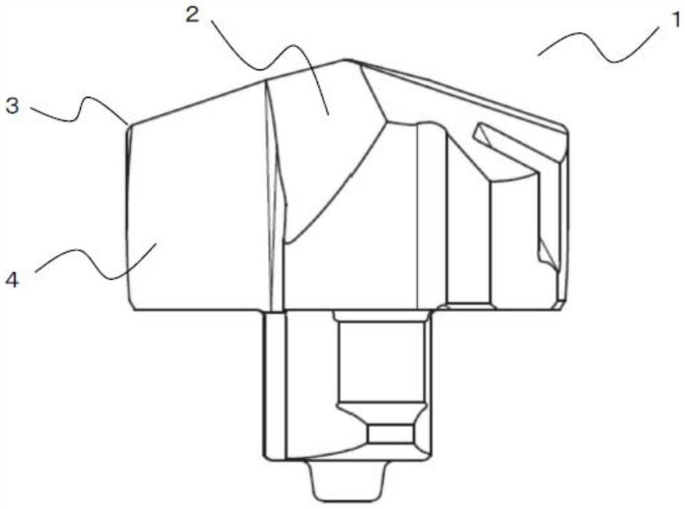
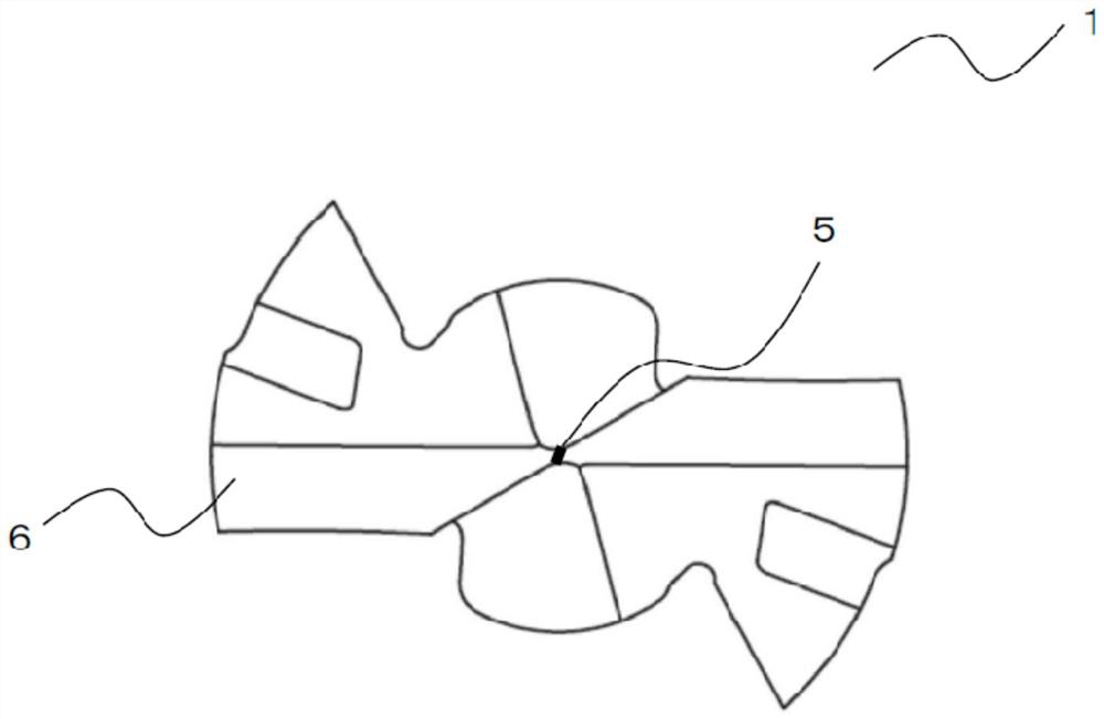
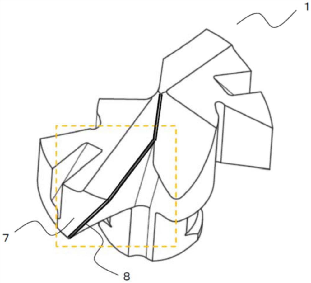
The purpose of the present invention is to provide a drill which has excellent defect resistance and wear resistance and which can extend the life of a tool. A drill in which a chip removal groove is formed in the outer periphery of a tip section, which is a tip-side portion of a drill body, and a cutting edge is formed in an intersecting ridge section between a rake face in a tip-side region and a tip flank face of the tip section, the drill having an edge section, a shoulder section, and a coping section, the cutting edge has a first cutting edge portion, a second cutting edge portion, a shoulder cutting edge portion, and an edge cutting edge portion in this order from the center of rotation, and when the honing width at a boundary P1 is R1 and the honing width at a position P2 spaced from the boundary P1 by 3 mm is R2, the honing width gradually decreases from the boundary P1 toward the position P2. The honing width of the second cutting edge portion is less than or equal to R1... (1) 2.0 lt, and the honing width of the second cutting edge portion is less than or equal to R1... (2). R1 / R2lt; 5.0... (2).

Description

technical field [0001] The present invention relates to a drill bit. Background technique [0002] Conventionally, in a drill for drilling, it has been known that the cutting edge is honed to make it difficult to cause a chipping. [0003] For example, Patent Document 1 proposes a drill in which a chip flute extending toward the rear end side is formed on the outer periphery of a tip portion, which is a front end portion of a drill body that rotates around an axis, and the flute is directed forward in the drill rotational direction. A cutting edge is formed on the intersecting ridgeline between the inner wall surface of the side and the front end flank of the cutting edge, and a dressing is formed on the front end side of the inner wall surface of the chip flute, which is connected to the inner peripheral end side of the cutting edge. Therefore, in the drill having the grinding cutting edge on the inner peripheral end side of the cutting edge, the cutting edge is honed, and...

Claims


Application Information

Patent Timeline
IPC IPC(8): B23B51/00
CPCB23B51/00B23B51/02B23B2251/125B23B2251/44B23B2228/10B23B2224/36B23B51/0002B23B2251/12
Inventor 片桐隆雄
Owner TUNGALOY CORP
Learn More