Machine tool and method for performing friction welding by utilizing machine tool
A friction welding and machine tool technology, used in welding equipment, non-electric welding equipment, other manufacturing equipment/tools, etc., can solve the problems of reducing the machining accuracy of the workpiece, increasing the number of workpiece clamping, and high costs, and achieves a smooth and smooth circumferential surface. The effect of welding
- Summary
- Abstract
- Description
- Claims
- Application Information
AI Technical Summary
Problems solved by technology
Method used
Image


Examples
Embodiment 1
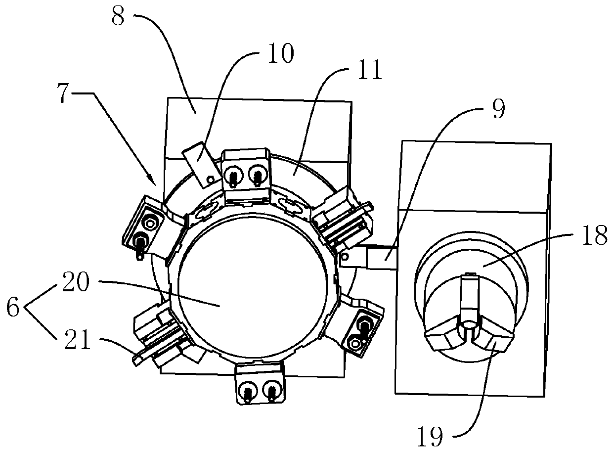
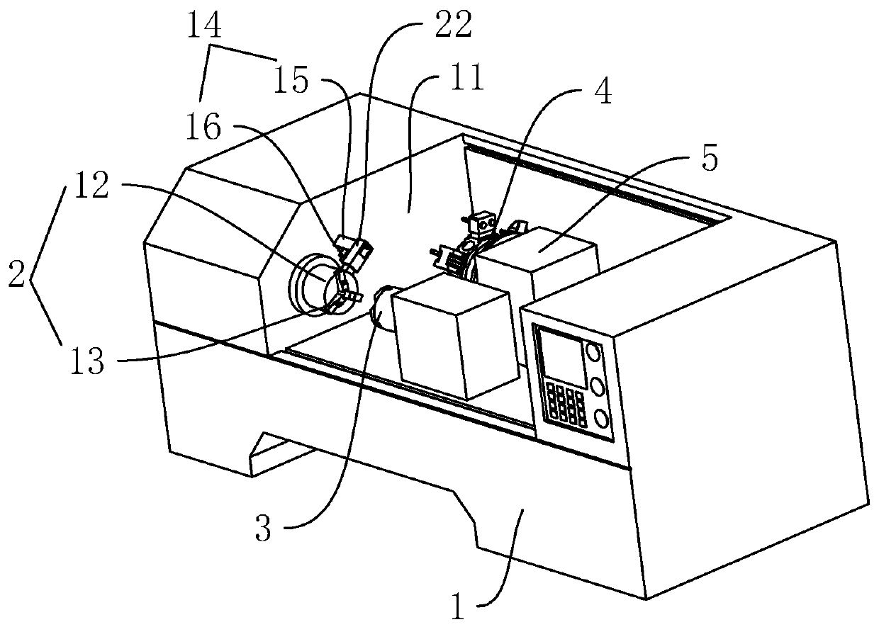
[0032] refer to figure 1 , is a kind of machine tool disclosed by the present invention, comprising a machine tool body 1, a first clamping device 2, a second clamping device 3 and an auxiliary device 4 are arranged on the machine tool body 1, and the auxiliary device 4 includes a The auxiliary table 5 on the surface, the cutting assembly 6 arranged on the auxiliary table 5, and the pressure compensation assembly 7 arranged on the auxiliary table 5; when two weldments are welded, one of the weldments is clamped in the first clamping On the device 2, another weldment is clamped on the second clamping device 3, the second clamping device 3 drives the weldment to move towards the first clamping device 2, and the first clamping device 2 drives the first weldment Rotating at high speed, when the second clamping device 3 drives the second weldment to move towards the first clamping device 2 and contacts the first weldment, the high-speed friction between the ends of the two weldment...
Embodiment 2
[0042] refer to figure 2 , is a kind of method that utilizes machine tool to carry out friction welding that the present invention discloses, comprises the following steps: S1, at first each axis returns to the origin, and two weldments are respectively clamped on the main shaft 12 and the auxiliary shaft 18; S2, the main shaft 12 rotates, At the same time, the sub-shaft 18 rotates and locks; S3, the sub-shaft 18 moves and locates, and the auxiliary table 5 drives the push block 9 to move to contact with the push plate 10; S4, the sub-shaft 18 and the turret 20 move at the same time, and drive the weldment to move to each other In the contact state, the friction heats up; S5, the rotation speed of the main shaft 12 is reduced to zero, the first three-jaw chuck 13 releases the workpiece, and the auxiliary shaft 18 drives the workpiece back at the same time.
[0043] In step S4, the sub-shaft 18 and the auxiliary table 5 move axially and remain still while driving the weldment ...
PUM
 Abstract
Description
Claims
Application Information
 - R&D
- Intellectual Property
- Life Sciences
- Materials
- Tech Scout
- Unparalleled Data Quality
- Higher Quality Content
- 60% Fewer Hallucinations
Browse by: Latest US Patents, China's latest patents, Technical Efficacy Thesaurus, Application Domain, Technology Topic, Popular Technical Reports.
© 2025 PatSnap. All rights reserved.Legal|Privacy policy|Modern Slavery Act Transparency Statement|Sitemap|About US| Contact US: help@patsnap.com