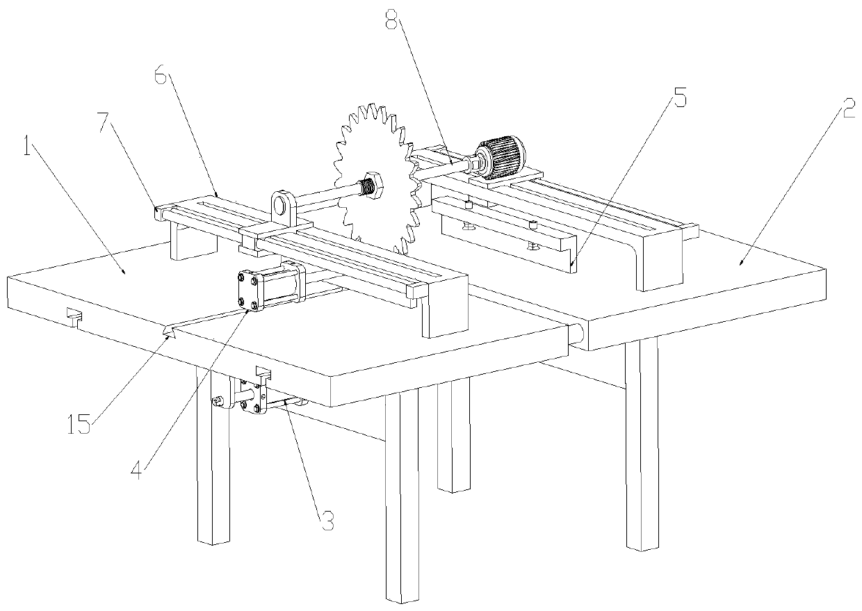
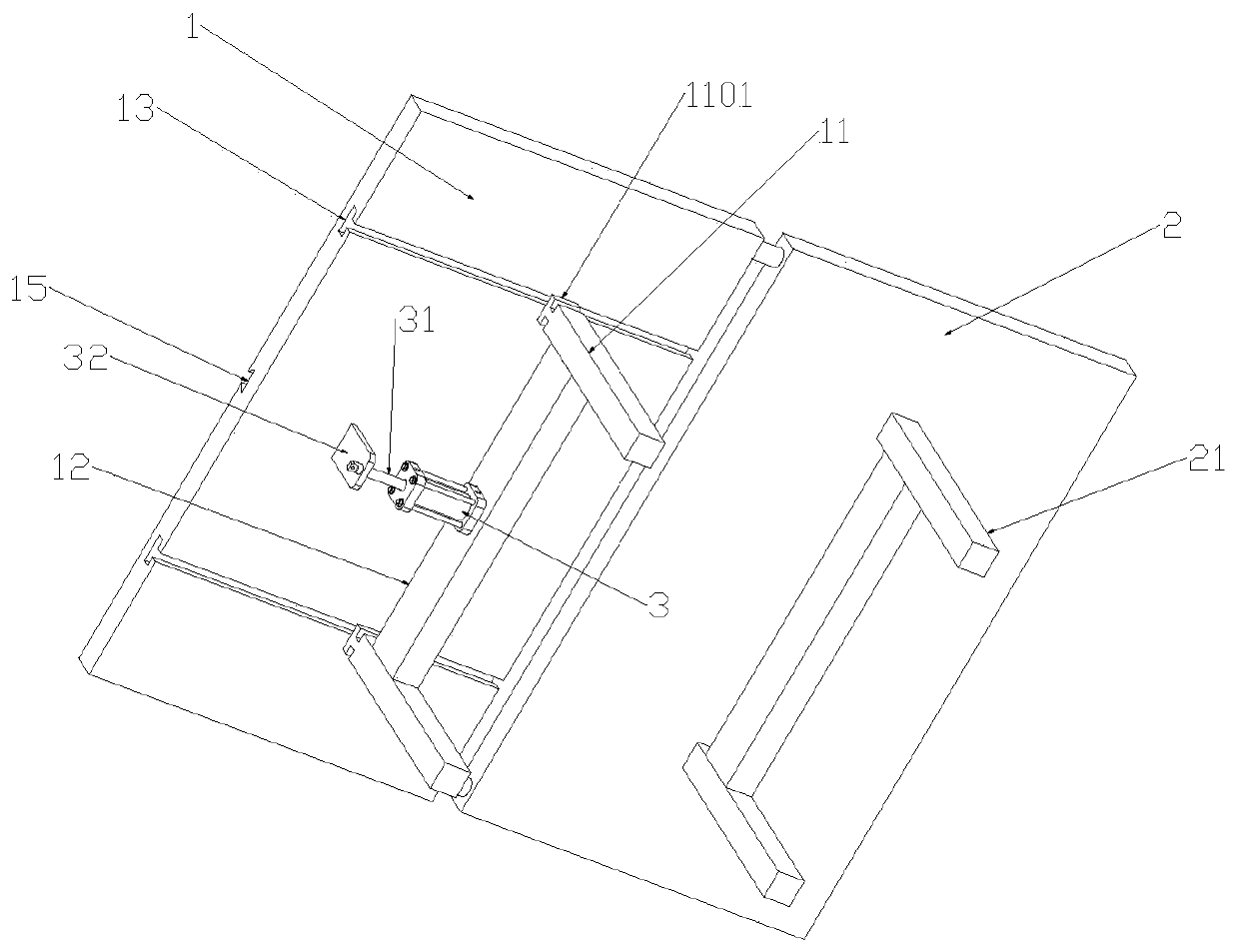
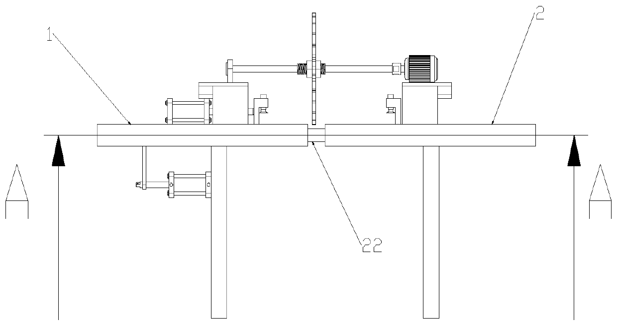
Automatic cutting device for producing and processing plate material through mold

An automatic cutting and plate technology, applied in metal processing and other directions, can solve the problems of operator's personal safety threat, actual production inconvenience, inconvenient cutting, etc., and achieve the effect of easy promotion, simple structure and convenient operation.

Active Publication Date: 2019-07-05
铜陵中锐电子科技有限公司
View PDF7 Cites 6 Cited by
  • Summary
  • Abstract
  • Description
  • Claims
  • Application Information

AI Technical Summary

Problems solved by technology

In the prior art, the cutting of the plate is generally by fixing one end of the plate and cutting the other end of the plate. After the cutting is completed, the plate at one end is fixed, and the plate at one end may collapse. pose a threat to the personal safety of personnel;
[0004] At the same time, since the relative position of the motor driving the cutting wheel and the plate is fixed, when cutting a larger plate, it is necessary to replace a larger cutting wheel, which is inconvenient to operate;
[0005] When the width of the cut plate needs to be changed, the relative position of the motor and the plate needs to be changed, which will also cause inconvenient cutting and bring inconvenience to the actual production

Method used


Image

  • Automatic cutting device for producing and processing plate material through mold
  • Automatic cutting device for producing and processing plate material through mold
  • Automatic cutting device for producing and processing plate material through mold

Examples


Embodiment Construction

[0036] The following will clearly and completely describe the technical solutions in the embodiments of the present invention with reference to the accompanying drawings in the embodiments of the present invention. Obviously, the described embodiments are only some, not all, embodiments of the present invention. Based on the embodiments of the present invention, all other embodiments obtained by persons of ordinary skill in the art without creative efforts fall within the protection scope of the present invention.

[0037] In describing the present invention, it is to be understood that the terms "opening", "upper", "lower", "thickness", "top", "middle", "length", "inner", "surrounding" etc. Indicating orientation or positional relationship is only for the convenience of describing the present invention and simplifying the description, and does not indicate or imply that the components or elements referred to must have a specific orientation, be constructed and operated in a sp...


PUM


Abstract

The invention discloses an automatic cutting device for producing and processing a plate material through a mold. The automatic cutting device comprises a first platen and a second platen, a dovetailgroove is formed in the middle position of the upper surface of the first platen, the upper end of the dovetail groove is provided with a second cylinder fixed to the upper end of the first platen, and one end of the second cylinder is connected with a clamping piece. Support frames provided with limiting grooves in the middle portions are fixed to the upper ends of the first platen and the secondplaten, linear electric cylinders are fixed to the side ends of the support frames, I-shaped bodies are fixed to the side ends of electric cylinder sliders, the upper ends of the I-shaped bodies arefixedly provided with cutting mechanisms. After cutting is completed, transverse positioning disappears, longitudinal positioning does not change, the plate material does not collapse, and the personal safety of an operator is not threatened; and meanwhile, when the width of the cut plate material needs to be changed, the position of a fastening nut is adjusted, the appropriate distance between acutting wheel and a clamping plate is obtained through measurement, the desired width of the plate material after cutting is obtained, and operation is convenient.

Description

technical field [0001] The invention relates to the processing field of mold production, in particular to an automatic cutting device for mold production and processing plates. Background technique [0002] Mold, various molds and tools used in industrial production to obtain the required products by die-casting or forging molding, etc. The mold is a tool used to make shaped objects. This tool is composed of various parts, and different molds are composed of different parts. constitute. [0003] The mold needs to cut and shape the raw material before processing, which is convenient for subsequent processing operations. In the prior art, the cutting of the plate is generally by fixing one end of the plate and cutting the other end of the plate. After the cutting is completed, the plate at one end is fixed, and the plate at one end may collapse. pose a threat to the personal safety of personnel; [0004] At the same time, since the relative position of the motor driving the...

Claims


Application Information

Patent Timeline
Patent Type & Authority Applications(China)
IPC IPC(8): B26D1/18B26D7/01B26D7/26
CPCB26D1/185B26D7/015B26D7/2628
Inventor 张先兵徐林张锋张传喜
Owner 铜陵中锐电子科技有限公司
Why Eureka
Try Eureka