Injection mold convenient for cooling molding

An injection mold, cooling and shaping technology, applied in the field of injection molds that are easy to cool and shape, can solve the problems of no cooling device for cooling circulating water, poor heat absorption efficiency of the mold, and long product molding time, so as to achieve fast flow speed and improve heat absorption Efficiency, the effect of lowering the temperature of the water

Inactive Publication Date: 2019-07-05
罗瑞琪
2 Cites 2 Cited by

AI-Extracted Technical Summary

Problems solved by technology

[0004] The purpose of the present invention is to provide an injection mold that is convenient for cooling and shaping, so as to solve the above-mentioned background technology that the existing injection mold cooling circulat...

Method used

By adopting above-mentioned technical scheme, the setting of dust-proof net 139 prevents the dust of outside, and impurities such as solid particles enter on the cooling box 131 in the cooling chamber 134 with air inlet 135 and air outlet 136, affect the heat dissipation of cooling box 131, It acts as a filter and protector.
By adopting above-mentioned technical scheme, the setting of filling port 16 is convenient to add water in water tank 10, and the setting of plugging 17 blocks filling port 16, prevents water from overflowing from filling port 16, plays sealing effect.
[0030] By adopting the above-mentioned technical s...

Abstract

The invention discloses an injection mold convenient for cooling molding. The injection mold comprises a movable mold base and a static mold base; the movable mold base is fixed on a movable worktable; the static mold base is fixed on a static worktable; a convex mold insert is fixed in middle of the movable mold base, and is inserted in a concave mold insert; the concave mold insert is fixed in middle of the static mold base; a heat absorbing pipe is wound on the outer side of the concave mold insert, and is positioned in the static mold base; a liquid inlet of the heat absorbing pipe communicates with a liquid outlet of a water pump through a liquid inlet pipe; a liquid inlet of the water pump communicates with a water tank through a water pipe; the water pump and the water tank are bothfixed in a mounting box; the mounting box is positioned under the movable mold base and the static mold base; a liquid outlet of the heat absorbing pipe communicates with a liquid outlet pipe; the liquid outlet pipe communicates with a heat dissipating mechanism; and one side of the heat dissipating mechanism communicates with the water tank. Through the structure, the quick cooling of the mold is realized, the cooling time is short, and the working efficiency is high.

Technology Topic

Image

  • Injection mold convenient for cooling molding
  • Injection mold convenient for cooling molding
  • Injection mold convenient for cooling molding

Examples

  • Experimental program(1)

Example Embodiment

[0023] The following will clearly and completely describe the technical solutions in the embodiments of the present invention with reference to the accompanying drawings in the embodiments of the present invention. Obviously, the described embodiments are only some, not all, embodiments of the present invention. The specific embodiments described here are only used to explain the present invention, not to limit the present invention. Based on the embodiments of the present invention, all other embodiments obtained by persons of ordinary skill in the art without making creative efforts belong to the protection scope of the present invention.
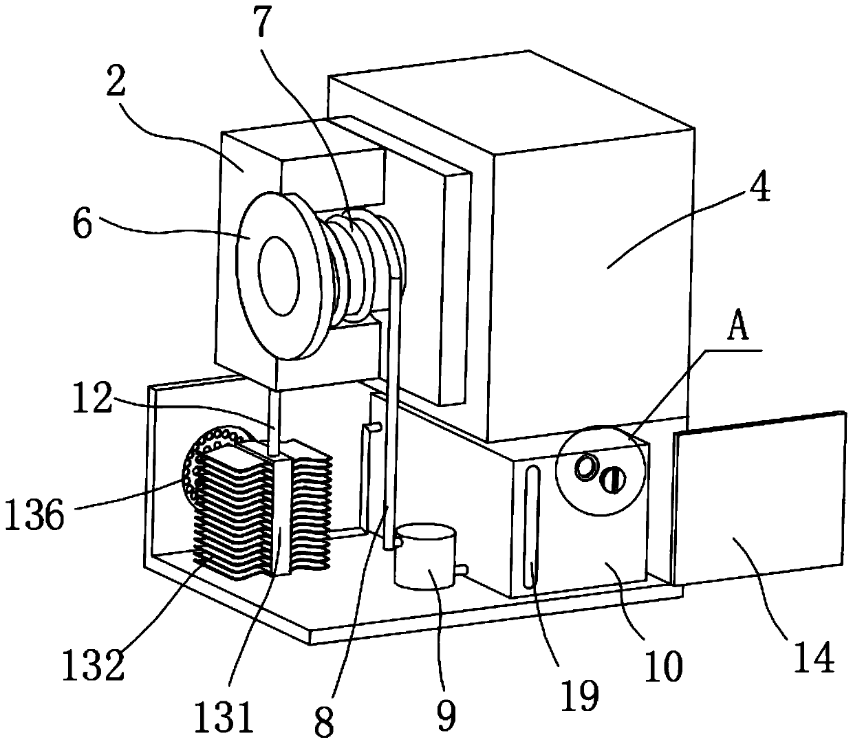
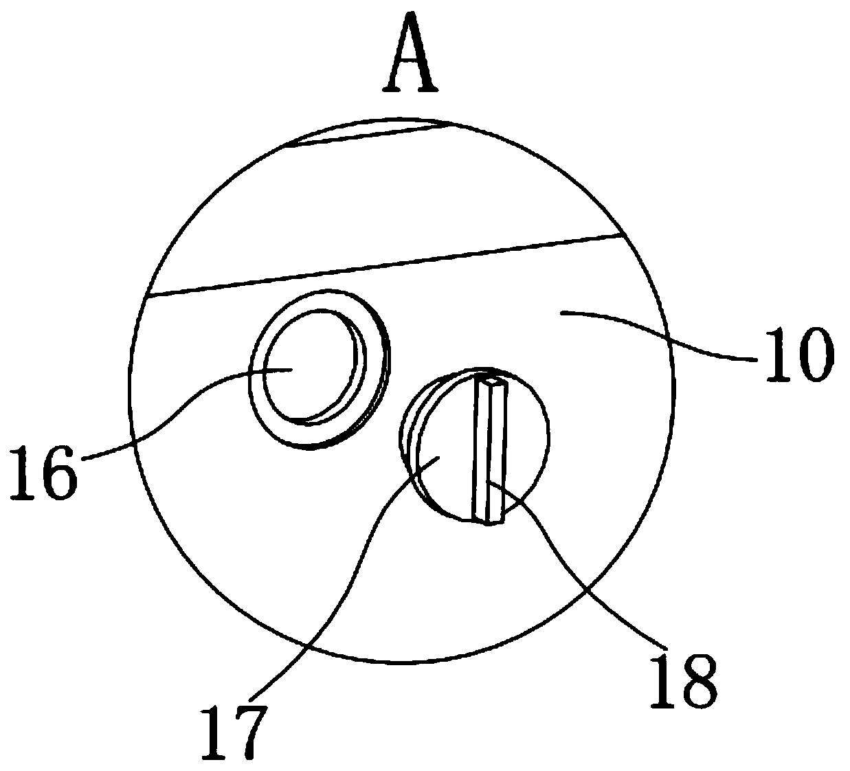
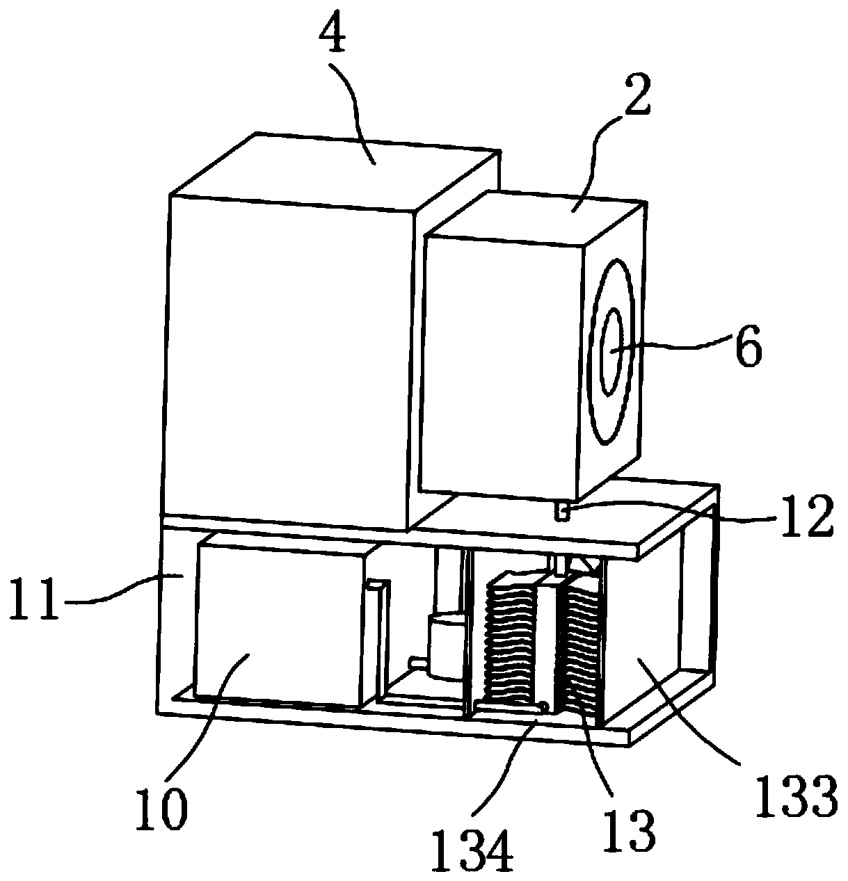
[0024] The present invention provides such Figure 1-5 The shown injection mold for cooling and shaping includes a movable mold base 1 and a static mold base 2, the movable mold base 1 is fixed on a mobile workbench 3, and the static mold base 2 is fixed on a static workbench 4 , the mobile workbench 3 and the static workbench 4 are all working parts of the injection molding machine, the middle of the movable mold base 1 is fixed with a punch insert 5, and the punch insert 5 is inserted into the die insert 6 Inside, the die insert 6 is fixed in the middle of the static die base 2, and the outer side of the die insert 6 is uniformly wound with a heat absorbing pipe 7, and the heat absorbing pipe 7 is located inside the static die base 2 , the liquid inlet of the heat-absorbing pipe 7 communicates with the liquid outlet of the water pump 9 through the liquid inlet pipe 8, and the liquid inlet of the water pump 9 communicates with the water tank 10 through the water pipe, and the water pump 9 and the water tank 10 are fixed on the installation Inside the box 11, the installation box 11 is located below the movable mold base 1 and the static mold base 2, the liquid outlet of the heat absorbing pipe 7 is connected with a liquid outlet pipe 12, and the liquid outlet pipe 12 is connected with a heat dissipation mechanism 13 , one side of the heat dissipation mechanism 13 communicates with the water tank 10 .
[0025] Preferably, the heat dissipation mechanism 13 includes a heat dissipation box 131, the liquid inlet of the heat dissipation box 131 communicates with the liquid outlet pipe 12, and both sides of the heat dissipation box 131 are provided with partitions 133, and the partitions 133 Fixed in the middle of the interior of the installation box 11, the two partitions 133 and the installation box 11 enclose a heat dissipation chamber 134, the heat dissipation box 131 is located in the interior of the heat dissipation chamber 134, and the front and rear ends of the heat dissipation chamber 134 are symmetrically arranged with The air inlet 135 and the air outlet 136, the air inlet 135 is provided with a mounting frame 137, the mounting frame 137 is fixed on the side wall of the installation box 11, and the fan 138 is fixed on the mounting frame 137.
[0026] By adopting the above-mentioned technical scheme, it plays the role of cooling the cooling water, so that the temperature of the water is rapidly reduced, and then enters the water tank 10 for circulating work, which reduces the temperature of the water and avoids the influence of the rise of the water temperature due to long-term work on the absorption of the mould. heat, which shortens the product molding time and improves work efficiency.
[0027] Preferably, both the air inlet 135 and the air outlet 136 are provided with a dust-proof net 139 , and the dust-proof net 139 is fixed on the side wall of the installation box 11 .
[0028] By adopting the above-mentioned technical scheme, the setting of the dust-proof net 139 prevents external dust, solid particles and other impurities from entering the heat dissipation box 131 in the heat dissipation chamber 134 with the air inlet 135 and the air outlet 136, which affects the heat dissipation of the heat dissipation box 131 and plays a role in filtering. ,Protective effects.
[0029] Preferably, several cooling fins 132 are evenly arranged on both sides of the cooling box 131, and the cooling fins 132 are arranged in a wave shape.
[0030] By adopting the above technical solution, the heat dissipation fins 132 are arranged in a wave shape, so that the heat dissipation area of ​​the heat dissipation fins 132 with the same length is increased, and the heat dissipation efficiency is improved.
[0031] Preferably, a box door 14 is hinged on one side of the installation box 11 , and a handle 15 is fixed on the end of the box door 14 away from the hinge.
[0032] By adopting the above technical scheme, it is convenient to open the box door 14 through the handle 15 by hand, and then add water to the water tank 10 in the installation box 11, which is convenient for work.
[0033] Preferably, the water tank 10 is provided with a liquid filling port 16 at the upper end of one side close to the tank door 14 , and a plug 17 is screwed on the liquid filling port 16 .
[0034] By adopting the above-mentioned technical scheme, the setting of the filling port 16 facilitates adding water into the water tank 10, and the setting of the plug 17 blocks the filling port 16 to prevent water from overflowing from the filling port 16 and play a sealing role.
[0035] Preferably, a knob 18 is fixed on the plug 17 .
[0036] By adopting the above-mentioned technical scheme, the setting of the knob 18 is convenient to turn the plug 17 by hand through the knob 18, so as to realize the opening and closing of the plug 17, which is convenient for work.
[0037] Preferably, an observation window 19 is provided on the side wall of the water tank 10 near the liquid filling port 16 .
[0038] By adopting the above-mentioned technical scheme, the setting of the observation window 19 is convenient for observing the amount of water in the water tank 10, so as to add it in time and facilitate the work.
[0039]Working principle: the mobile worktable 3 on the injection molding machine moves forward, and then the movable mold base 1 moves forward with the movable worktable 3 until the convex mold insert 5 on the movable mold base 1 is inserted into the concave hole in the static mold base 2 mold insert 6 to achieve mold closing, and then the injection molding machine injects liquid material into the mold cavity formed by the punch insert 5 and the die insert 6, and the water pump 9 is started at the same time as the material is injected, and then the water pump 9 turns the water tank 10 The water inside is transported through the liquid inlet pipe 8 to the heat-absorbing pipe 7 wound outside the die insert 6, the flowing water continuously absorbs the heat around the mold, and then the temperature of the mold and the material in the cavity is lowered, and the material is cooled to realize molding ;
[0040] The water that has absorbed the heat flows into the cooling tank 131 from the heat-absorbing pipe 7 by the liquid outlet pipe 12, and then flows into the cooling fins 132. 138 starts, and then generates wind force, and the wind blows the heat in the heat dissipation chamber 134 out of the heat dissipation chamber 134 through the air outlet 136, and then realizes the cooling and heat dissipation of the water. Realize the circulation of cooling water.
[0041] Finally, it should be noted that: the above is only a preferred embodiment of the present invention, and is not intended to limit the present invention. Although the present invention has been described in detail with reference to the foregoing embodiments, for those skilled in the art, it still It is possible to modify the technical solutions recorded in the foregoing embodiments, or to perform equivalent replacements on some of the technical features. Any modifications, equivalent replacements, improvements, etc. within the spirit and principles of the present invention shall be included in the within the protection scope of the present invention.

PUM

no PUM

Description & Claims & Application Information

We can also present the details of the Description, Claims and Application information to help users get a comprehensive understanding of the technical details of the patent, such as background art, summary of invention, brief description of drawings, description of embodiments, and other original content. On the other hand, users can also determine the specific scope of protection of the technology through the list of claims; as well as understand the changes in the life cycle of the technology with the presentation of the patent timeline. Login to view more.

Similar technology patents

Novel pressure injection mold

InactiveCN105703200AReduce wasteFast flowCommutators manufacturePressure injectionMechanical engineering
Owner:贺广民

Classification and recommendation of technical efficacy words

  • Fast flow
  • Improve heat absorption efficiency

Fast drainage safety floor drain

InactiveCN101691779ASmooth inflow of stagnant waterFast flowSewerage structuresEngineeringGround water flow
Owner:戴永锋

Filter plate assembly used in filter press

Owner:江苏知聚知识产权服务有限公司

Solar heat collector and seawater desalination system comprising same

InactiveCN105588342AAvoid thermal blind spotsImprove heat absorption efficiencySolar heating energyGeneral water supply conservationSeawaterSolar thermal collector
Owner:山东大学(威海)

Evaporator core

Owner:TONGLING HUIYU IND CO LTD

Stirling heat engine solar heat collector

ActiveCN103629829AUniform temperatureImprove heat absorption efficiencySolar heating energySolar heat devicesAbsorption rateStirling engine
Owner:斯特林威索AB

Lubricating oil self-circulating system of bearing box for pump

ActiveCN107269571AMaintain delivery pressureImprove heat absorption efficiencyPump componentsPumpsOil storageOil intake
Owner:重庆水泵厂有限责任公司

LED lamp with water-circulating heat dissipation function

ActiveCN105221970AImprove heat absorption efficiencyEven heat absorptionPoint-like light sourceLighting heating/cooling arrangementsHeat sinkEngineering
Owner:JIANGSU TIWIN OPTO ELECTRONICS TECH
Why Eureka
Try Eureka