Laser film cutting and laminating machine

A technology of laser cutting and laminating mechanism, applied in laser welding equipment, manufacturing tools, chemical instruments and methods, etc., can solve the problems of low cutting precision, low work efficiency, and easily damaged products, etc., to save film and improve processing. Efficiency and high precision

Active Publication Date: 2021-03-05
苏州美力美机械设备有限公司
View PDF10 Cites 0 Cited by
  • Summary
  • Abstract
  • Description
  • Claims
  • Application Information

AI Technical Summary

Problems solved by technology

[0002] The film cutting and laminating machine in the prior art needs to leave a certain distance between adjacent products transmitted on the transmission line before laminating, and cut through the servo module or the rodless cylinder with the cutter; due to the product transmission There is a deviation in the process, which leads to the situation that the distance between adjacent products is large on one side and small on the other, that is, the product is tilted. In this case, the cutter is easy to damage the product; the cutter can only complete the large distance and straight line. Cutting, after the cutter cuts off the film material, there will be excess film material at both ends of the product, which needs manual trimming
[0003] Therefore, the existing film cutting and laminating machines have low work efficiency, low cutting precision and high energy consumption.

Method used


Image

  • Laser film cutting and laminating machine
  • Laser film cutting and laminating machine
  • Laser film cutting and laminating machine

Examples


Embodiment Construction

[0024] The present invention will be further described below in conjunction with the accompanying drawings and specific embodiments.

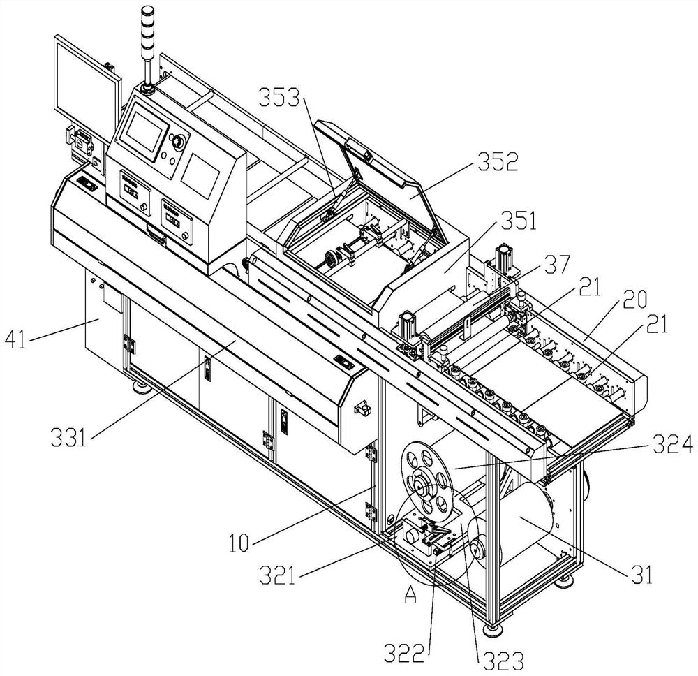
[0025] Such as Figure 1 to Figure 4 As shown, the laser cutting film laminating machine includes a frame 10, a conveying roller table 20 for linearly conveying the plate is arranged above the frame 10, a plate laminating mechanism and a laser film cutting mechanism are arranged in the frame 10, and the frame One side of the laser tube 10 is provided with a laser tube protective case 331; the conveying roller table 20 adopts a power roller, which can continuously transport the sheet material forward. Positioning rollers 21 are also installed between the entrance and the mold roller assembly; the plate coating mechanism includes a film roller device, a release paper collection roller 31 and a film roller assembly, and the release paper collection roller 31 is installed on the top of the film roller device. In the front, the laminating roller as...


PUM


Abstract

The invention relates to the technical field of film cutting and coating processing equipment, and discloses a laser cutting and coating machine, including a frame, a conveying roller table, a plate coating mechanism, a laser cutting mechanism, a laser chiller, a control device, a display and an alarm light , the conveying roller table is installed above the frame, the plate laminating mechanism and the laser film cutting mechanism are installed in the frame, the plate laminating mechanism is installed in front of the laser film cutting mechanism, and the control device is respectively connected with the conveying roller table and the plate laminating mechanism. Mechanism, laser film cutting mechanism, display, and warning light are electrically connected; positioning rollers are also arranged on the conveying roller table; the laser film cutting mechanism includes a laser tube, a laser film cutting base, an XY axis transmission device, a laser head, a camera, Bar lights and reflectors. The positioning roller is set to ensure that the plate is kept in a straight line during the transmission process; the industrial CCD camera and XY axis transmission device are set to enable the laser film cutting mechanism to cut the beveled edge with high precision and no need for manual trimming after cutting, which improves the processing efficiency.

Description

technical field [0001] The invention relates to the technical field of film cutting and coating processing equipment, in particular to a laser cutting and coating machine. Background technique [0002] The film cutting and laminating machine in the prior art needs to leave a certain distance between adjacent products transmitted on the transmission line before laminating, and cut through the servo module or the rodless cylinder with the cutter; due to the product transmission There is a deviation in the process, which leads to the situation that the distance between adjacent products is large on one side and small on the other, that is, the product is tilted. In this case, the cutter is easy to damage the product; the cutter can only complete the large distance and straight line. Cutting, after the cutter cuts off the film material, there will be excess film material at both ends of the product, which needs to be manually trimmed. [0003] Therefore, the existing film cutti...

Claims


Application Information

Patent Timeline
Patent Type & Authority Patents(China)
IPC IPC(8): B32B37/10B32B38/04B23K26/08B23K26/146B23K26/38B23K26/70
CPCB23K26/0876B23K26/38B32B37/10B32B38/04B32B2038/045B23K26/146B23K26/702
Inventor 韩仕亮韩培立
Owner 苏州美力美机械设备有限公司
Why Eureka
Try Eureka