Lens module production equipment

A lens module and production equipment technology, applied in installation, optics, instruments, etc., can solve the problems of reduced splicing efficiency, increased equipment cost and maintenance cost, etc., to save equipment cost and maintenance cost, save equipment cost, and improve splicing. The effect of efficiency

Active Publication Date: 2021-03-30
浙江蓝海光学科技有限公司
View PDF1 Cites 0 Cited by
  • Summary
  • Abstract
  • Description
  • Claims
  • Application Information

AI Technical Summary

Problems solved by technology

[0003] The existing patent No. CN102463573B proposes the assembly equipment of the lens module, which is assembled by sucking the frame through the suction nozzle mechanism, but when assembling, it is necessary to place the frame in a relative state before splicing, and the angle adjustment is added in the splicing operation mechanism and operation, resulting in a decrease in splicing efficiency, and when the frame is transported to the splicing mechanism through a conveyor belt, it is necessary to detect data such as the position of the frame through multiple sensors to achieve automatic splicing and other operations, resulting in a substantial increase in equipment costs and maintenance costs

Method used


Image

  • Lens module production equipment
  • Lens module production equipment
  • Lens module production equipment

Examples


Embodiment 1

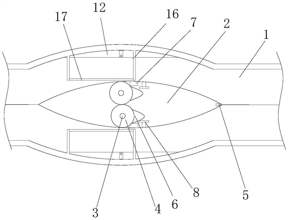
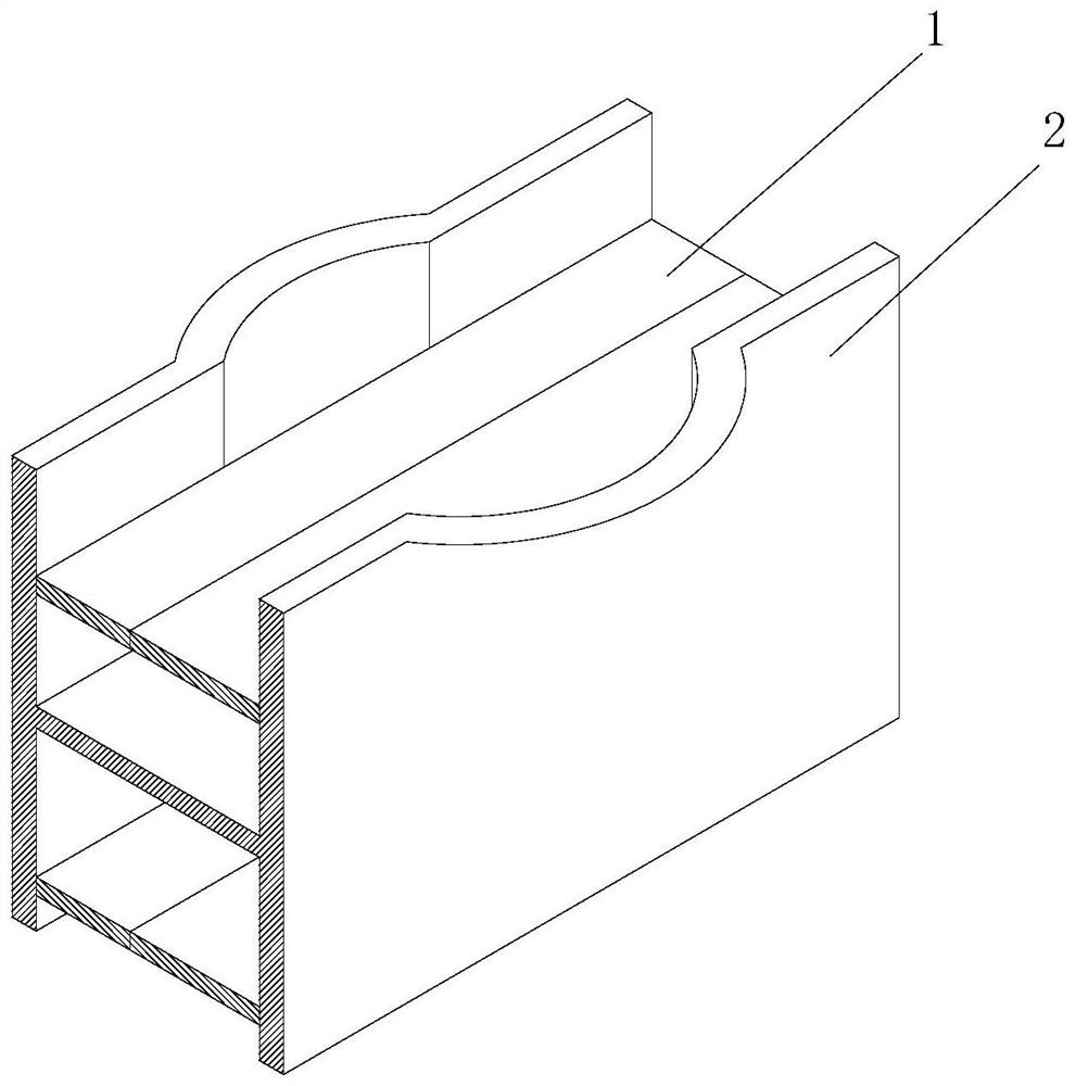
[0044] Example 1: Please refer to Figure 1-5 , the production equipment of the lens module, including the transmission belt 1 and the transmission table 2, the number of the transmission belt 1 is two and the front and back are in a corresponding state, the corresponding sides of the two transmission belts 1 are in a bonded state, and the two transmission belts 1 Both are connected with a transmission mechanism, the transmission belt 1 and the transmission mechanism are existing known technologies, the transmission belt 1 is made to rotate through the transmission mechanism, so as to transport the articles on the transmission belt 1, and will not repeat them here. The shape of the table 2 is rectangular and the top surface is provided with a rectangular groove. The transmission table 2 is located in the middle of the inner ring of the transmission belt 1. Two rotating bearings are fixedly installed in the center of the top surface of the transmission table 2. The inner ring of...

Embodiment 2

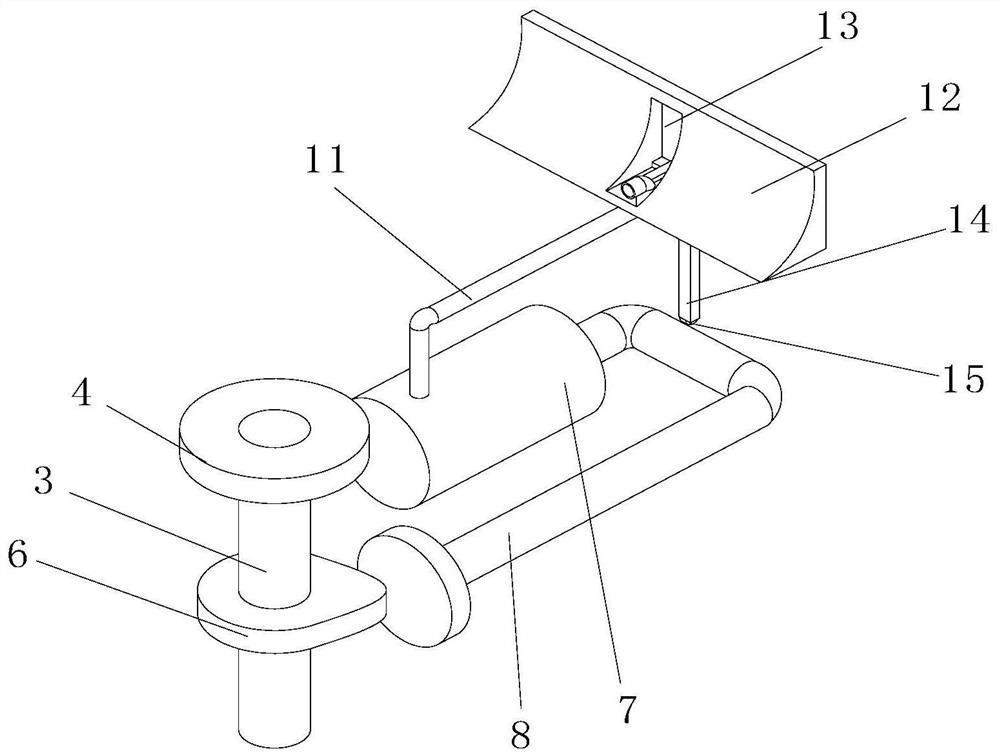
[0047] Example 2: Please refer to Figure 6-11 , on the basis of Embodiment 1, splicing plate A18 is placed on the conveyor belt 1, and the shape of splicing plate A18 is a T-shaped body. 19 is fan-shaped, and the two guide plates 19 are opposite. The sides of the two guide plates 19 away from the splicing plate A18 are respectively fixedly connected to the front and rear inner walls of the transfer table 2. The splicing plate A18 is located at the left end of the transfer table 2. , the top of the right side of the splicing plate A18 is fixedly connected with two lens barrels 20 respectively, the lens barrel 20 is a rectangular body hollowed out on the top surface, the top surface of the lens barrel 20 is hollowed out, and the left side inner wall of the lens barrel 20 is fixedly connected with Return spring B21, the unfixed end of return spring B21 is fixedly connected with push plate 22, and the inner wall of the top surface on the left side of lens barrel 20 is provided wi...

Embodiment 3

[0050] Example 3: Please refer to Figure 12-13 , on the basis of Embodiment 2, the front and rear inner walls of the transfer table 2 are fixedly connected with two splicing plates B34 on the right side of the splicing plate A18, and the gap between the diameters of the two splicing plates B34 is consistent with the thickness of the two frames connected. The corresponding side of A18 and splicing plate B34 is all provided with chute 35, and in the left and right corresponding chute 35, all is socketed with a slide plate 36, and the right end of slide plate 36 is magnet material and is opposite to the magnetic pole on the left side of strong magnet A28, two The corresponding side of the slide plate 36 is fixedly connected with a slider 37. Through the setting of the splicing plate B34, the frame for installing the lens is automatically spliced, which is conducive to further improving the production efficiency of the lens module, and does not require external power and sensing d...


PUM


Abstract

The invention relates to the technical field of lens modules, and discloses production equipment for lens modules, including a transmission belt and a transmission platform. Through the setting of the transmission belt, the two transmission belts are synchronously driven and then separated in the middle, so that the frame can be separated during the transmission process. Automatically separate the upper frame and the lower frame for transmission. While realizing the synchronous transmission function of the upper frame and the lower frame, it avoids the mixing of the upper frame and the lower frame of the frame during the transmission process. After the body and the lower frame are separated, during the transmission process, the sliding table and other structures are automatically turned to 90 degrees and the installation grooves are in a corresponding state, so that the upper frame and the lower frame are in an opposite state. The push mechanism can splice the upper frame and the lower frame with each other, which helps to improve the splicing efficiency and reduce the cost of the mechanism, and the power of the slide table and other structures is the operation of the transmission belt, which can realize the synchronization with the transmission belt To run, you only need to pay attention to the pitch of the frame.

Description

technical field [0001] The invention relates to the technical field of lens modules, in particular to production equipment for lens modules. Background technique [0002] The lens module is a module in which the lens and other mechanisms are installed through the frame. The frame is divided into an upper frame and a lower frame. During the production process of the lens module, it needs to be installed in the upper frame and the lower frame. lens, and then splice the corresponding sides of the upper frame and the lower frame together. [0003] The existing patent No. CN102463573B proposes the assembly equipment of the lens module, which is assembled by sucking the frame through the suction nozzle mechanism, but when assembling, it is necessary to place the frame in a relative state before splicing, and the angle adjustment is added in the splicing operation mechanism and operation, resulting in a decrease in splicing efficiency, and when the frame is transported to the spli...

Claims


Application Information

Patent Timeline
Patent Type & Authority Patents(China)
IPC IPC(8): B65G47/248B65G47/88B65G15/00B65G47/82G02B7/02
CPCB65G47/248B65G47/88B65G15/00B65G47/82G02B7/02
Inventor 章利炳李青松
Owner 浙江蓝海光学科技有限公司
Why Eureka
Try Eureka