Needle bar stroke adjustment structure, sewing machine with the same and stroke adjustment method
A technology of needle bar stroke and adjustment structure, which is applied to sewing machine components, needle bases for sewing machines, sewing equipment, etc., can solve the problems of difficult adjustment and cumbersome adjustment process, so as to reduce processing difficulty and processing cost, improve adaptability, The effect of improving efficiency
- Summary
- Abstract
- Description
- Claims
- Application Information
AI Technical Summary
Problems solved by technology
Method used
Image


Examples
Embodiment 1
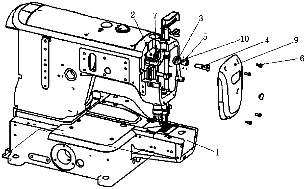
[0039] see Figure 1-5 , this embodiment provides a needle bar stroke adjustment structure, which is used to adjust the needle bar stroke of a sewing machine, and includes a needle bar crank 2, a needle bar connecting rod 3, a needle bar pin 4, an eccentric wheel 5 and a positioning member 6, Gaskets 7 and seals 8 may also be included. In this embodiment, the needle bar stroke adjustment structure is arranged inside the casing 1 of the sewing machine, and is the structure of the sewing machine. In addition to adjusting the stroke of the needle bar, the needle bar stroke adjustment structure can also be used as a device for driving the needle bar to move up and down, so that the needle bar can perform sewing work.
[0040] The needle bar crank 2 is rotatably installed on the casing 1 of the sewing machine, and can be driven by the driving structure of the sewing machine to rotate. The center line of the needle bar crank 2 is perpendicular to the needle bar of the sewing machi...
Embodiment 2
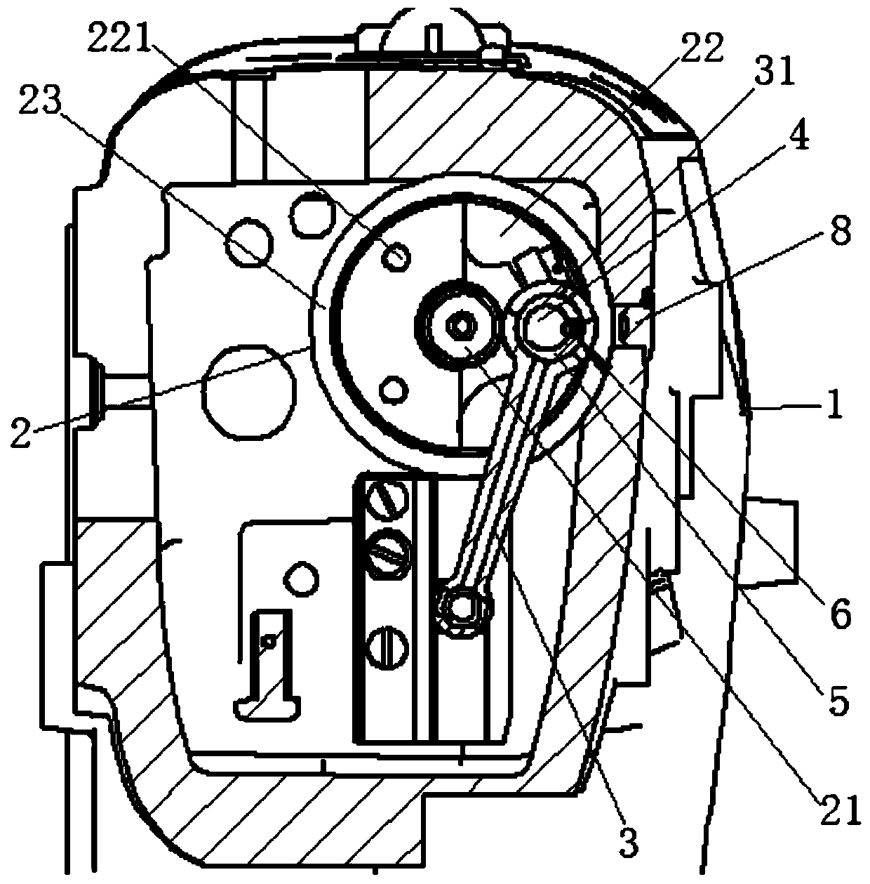
[0051] This embodiment provides a sewing machine which is convenient for adjusting the stroke of the needle bar, which includes a casing 1, a needle bar and a stroke adjusting device. In this embodiment, the stroke adjustment device is the needle bar stroke adjustment structure introduced in Embodiment 1. Both the needle bar and the stroke adjusting device are installed on the casing 1, and the stroke adjusting device is used to adjust the lifting range of the needle bar. The needle bar crank 2 is rotatably installed on the casing 1, and one end of the needle bar connecting rod 3 is rotatably connected with the needle bar.
[0052] Wherein, when adjusting the stroke of the needle bar, the operator moves the positioning piece 6 radially outward along the eccentric wheel 5 and breaks away from the taper hole, so that the other end of the positioning piece 6 is limited by the needle bar connecting rod 3, and the needle bar is connected. The rod 3 drives the eccentric wheel 5 to ...
Embodiment 3
[0055] This embodiment provides a needle bar stroke adjustment method, which is applied in the needle bar stroke adjustment structure in Embodiment 1. The needle bar stroke adjustment method includes the following steps:
[0056] 1. Move the positioning piece 6 radially outward along the eccentric wheel 5, so that the other end of the positioning piece 6 is limited by the needle bar connecting rod 3;
[0057] 2. Drive the eccentric wheel 5 to rotate, and change the distance between the center line of the mounting hole 31 and the center line of the needle bar crank 2;
[0058] 3. After adjusting the angle of the positioning piece 6, insert one end of the positioning piece 6 into the taper hole, so that the needle bar pin 4 and the eccentric wheel 5 are relatively fixed.
[0059] The method for adjusting the stroke of the needle bar in this embodiment is convenient for adjusting the stroke, and can correspondingly reduce the operating requirements of the operator, so that non-te...
PUM
 Abstract
Description
Claims
Application Information
 - R&D
- Intellectual Property
- Life Sciences
- Materials
- Tech Scout
- Unparalleled Data Quality
- Higher Quality Content
- 60% Fewer Hallucinations
Browse by: Latest US Patents, China's latest patents, Technical Efficacy Thesaurus, Application Domain, Technology Topic, Popular Technical Reports.
© 2025 PatSnap. All rights reserved.Legal|Privacy policy|Modern Slavery Act Transparency Statement|Sitemap|About US| Contact US: help@patsnap.com