Novel dry-type clutch

A dry clutch, a new type of technology, applied in the direction of clutches, mechanical drive clutches, mechanical equipment, etc., can solve the problems of complex structure, inconvenient disassembly and assembly, and achieve the effect of simple structure and convenient disassembly

Inactive Publication Date: 2019-07-05
宁波捷凯机械制造有限公司
0 Cites 0 Cited by

AI-Extracted Technical Summary

Problems solved by technology

[0004] The problem to be solved by the present invention is to provide a new type of dry clutch to ...

Abstract

The invention provides a novel dry-type clutch. The novel dry-type clutch comprises a first main body and a second main body, and the first main body and the second main body are made of an aluminum alloy; the first main body and the second main body are fixed in an inserted mode; a groove for placing a sealing ring is formed in the first main body; the first main body is further provided with a connecting bulge in an integral forming mode; the first main body is internally further provided with a shock absorption device; and a thread stud is further arranged on one side of the second main body. According to the novel dry-type clutch, the structure is simple, and the disassembly and assembly are convenient.

Application Domain

Mechanical actuated clutches

Technology Topic

ClutchBiomedical engineering +1

Image

  • Novel dry-type clutch
  • Novel dry-type clutch

Examples

  • Experimental program(1)

Example Embodiment

[0011] The specific embodiments of the present invention will be described in further detail below in conjunction with the drawings and embodiments. The following examples are used to illustrate the present invention, but not to limit the scope of the present invention.
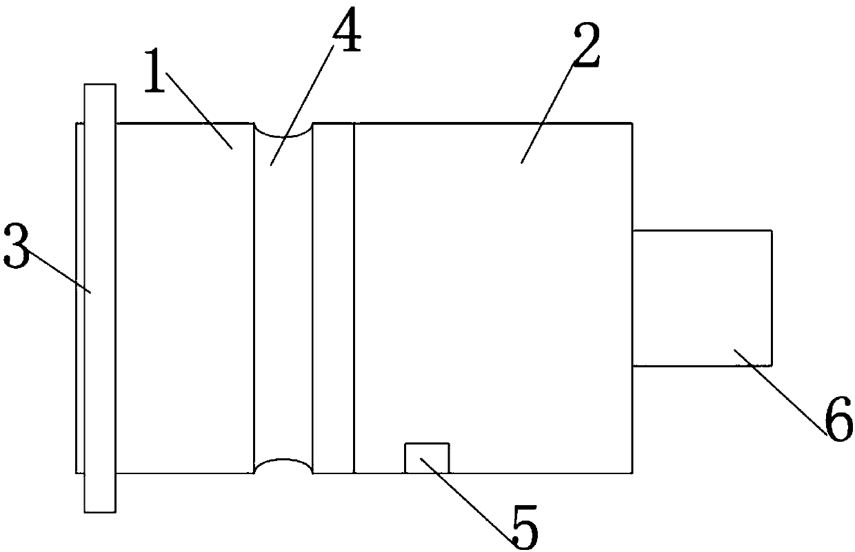
[0012] Such as figure 1 As shown, a new dry clutch of the present invention includes a first body 1 and a second body 2. The first body 1 and the second body 2 are made of aluminum alloy; the first body 1 and the The second body 2 is plugged and fixed; the first body 1 is provided with a groove 4 for placing a sealing ring; the first body 1 is also integrally formed with a connecting protrusion 3; the first body 1 is also provided There is a shock absorber 5; a stud 6 is also provided on one side of the second main body 2. The length of the first body is 12±0.2 cm.
[0013] In summary, the foregoing embodiments are not limited embodiments of the present invention. Any modification or equivalent modification made by those skilled in the art on the basis of the essence of the present invention falls within the technical scope of the present invention.

PUM

no PUM

Description & Claims & Application Information

We can also present the details of the Description, Claims and Application information to help users get a comprehensive understanding of the technical details of the patent, such as background art, summary of invention, brief description of drawings, description of embodiments, and other original content. On the other hand, users can also determine the specific scope of protection of the technology through the list of claims; as well as understand the changes in the life cycle of the technology with the presentation of the patent timeline. Login to view more.

Similar technology patents

Photoelectric sensor for position of sun

InactiveCN101650173AEffective tracking range expandedSimple structure
Owner:WUHAN UNIV OF TECH

Magnetic cooling apparatus and control method thereof

ActiveUS20130180263A1simple structure
Owner:SAMSUNG ELECTRONICS CO LTD

Dual-Drivetrain of Power-Assist Vehicle

InactiveUS20100181130A1enhance uphill momentumsimple structure
Owner:CHOU WEN CHENG

Classification and recommendation of technical efficacy words

Why Eureka
Try Eureka