
Mechanical fixed-point time-delay device

A delay device and mechanical technology, applied in the direction of mechanical equipment, transmission devices, transmission device parts, etc., can solve the problems of inability to improve the working efficiency of the delay device, the inability to increase the transmission efficiency, the inconvenience of fixed-point delay transmission, etc., and achieve structural Simple and flexible, reducing wear and increasing service life

Inactive Publication Date: 2019-07-05
陈瑞言
View PDF0 Cites 3 Cited by
  • Summary
  • Abstract
  • Description
  • Claims
  • Application Information

AI Technical Summary

Problems solved by technology

[0004] In some transmission mechanisms, it needs to be transmitted to the driven shaft with a delay, and it is required that the driven shaft rotate again when the active part rotates to a certain position. For example, some robot arms need to be controlled during the advancement process. The existing fixed-point delay device is not convenient to realize fixed-point delay transmission, and cannot increase the transmission efficiency. It is not a purely mechanical structure, and cannot avoid the influence of electromagnetic interference on the transmission mechanism, and cannot improve the working efficiency of the delay device.

Method used


Image

  • Mechanical fixed-point time-delay device
  • Mechanical fixed-point time-delay device
  • Mechanical fixed-point time-delay device

Examples


Embodiment Construction

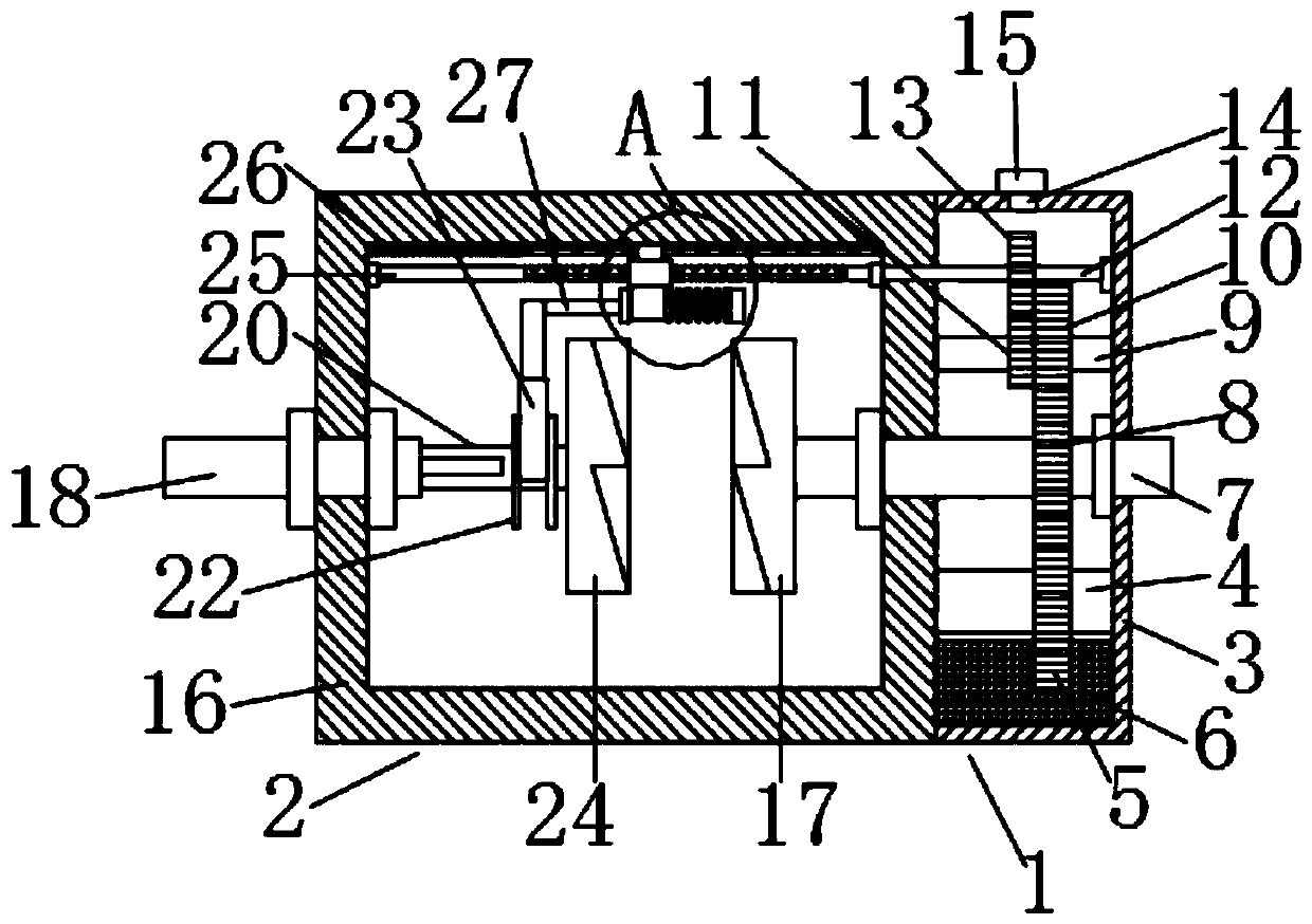
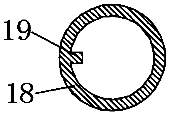
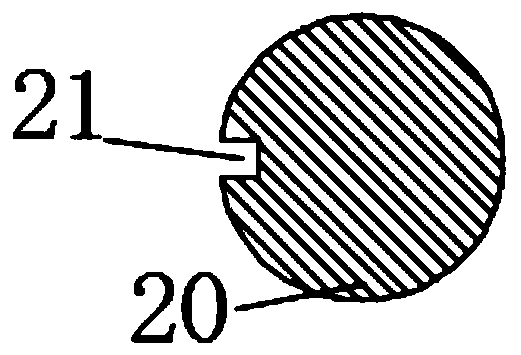
[0026] Such as Figure 1-5 As shown, this specific embodiment adopts the following technical solutions: a mechanical fixed-point delay device, including a reduction mechanism 1 and a transmission mechanism 2, and the reduction mechanism 1 is composed of a reduction box 3, a first rotating shaft 4, a lubrication gear 5, a lubrication Composed of oil 6, transmission input shaft 7, first gear 8, second rotating shaft 9, second gear 10, third gear 11, transmission rod 12, fourth gear 13, oil filling port 14 and sealing cover 15, the reduction box The middle part of 3 is inserted with transmission input shaft 7, and described transmission input shaft 7 is rotationally connected with reduction box 3, and the inside of described reduction case 3 and is positioned at the bottom of transmission input shaft 7 and is rotationally connected with first rotating shaft 4, and described first rotating shaft The outer side of 4 is fixedly covered with a lubricating gear 5, and the outer side o...


PUM


Abstract

The invention discloses a mechanical fixed-point time-delay device. The device comprises a speed reducing mechanism and a transmission mechanism, The speed reducing mechanism is composed of a speed reducing box, a first rotating shaft, a lubricating gear, a lubricating oil, a transmission input shaft, a first gear, a second rotating shaft, a second gear, a third gear, a transmission rod, a fourthgear, an oil injection port and a sealing cover; the transmission input shaft is inserted in the middle of the speed reducing box. According to the mechanical fixed-point time-delay device, the speedreducing box and a plurality of reduction gears are arranged, the lubricating oil can be conveniently lifted under the action of the lubricating gear, so that the upper transmission gear is lubricated, the abrasion between the gears is reduced, the service life of the gear is prolonged, the transmission rod is driven to rotate while the transmission input shaft rotates, the fixed-point time-delaytransmission is conveniently realized on the reciprocating screw rod and the pulling clamping plate, the transmission efficiency is increased, manual operation is not needed, the device is of a pure mechanical structure, so that the influence of electromagnetic interference on the transmission mechanism is avoided, and the working efficiency of the time-delay device is improved.

Description

[0001] Technical field: [0002] The invention belongs to the technical field of delay devices, in particular to a mechanical fixed-point delay device. [0003] Background technique: [0004] In some transmission mechanisms, it needs to be transmitted to the driven shaft with a delay, and it is required that the driven shaft rotate again when the active part rotates to a certain position. For example, some robot arms need to be controlled during the advancement process. The existing fixed-point delay device is inconvenient to realize fixed-point delay transmission, and cannot increase transmission efficiency. It is not a purely mechanical structure, and cannot avoid electromagnetic interference from affecting the transmission mechanism, and cannot improve the working efficiency of the delay device. [0005] Invention content: [0006] The object of the present invention is to provide a mechanical fixed-point delay device in order to solve the above problems, which solves the s...

Claims


Application Information

Patent Timeline
Patent Type & Authority Applications(China)
IPC IPC(8): F16H35/12F16H57/04
CPCF16H35/12F16H57/0457
Inventor 陈瑞言
Owner 陈瑞言
Learn More