
Calibration system and calibration method

A technology of calibration system and vision system, applied in instruments, measuring devices, resistors, etc., can solve the problems of discarding, waste, etc., and achieve the effect of reducing scrap rate, saving manufacturing cost, and reducing manufacturing difficulty

Active Publication Date: 2022-03-18
TYCO ELECTRONICS (SHANGHAI) CO LTD +2
View PDF0 Cites 0 Cited by
  • Summary
  • Abstract
  • Description
  • Claims
  • Application Information

AI Technical Summary

Problems solved by technology

[0003] In the prior art, if the resistance of the manufactured electronic device is not within the predetermined range, the electronic device becomes a waste product and will be discarded directly, which will cause great waste

Method used


Image

  • Calibration system and calibration method
  • Calibration system and calibration method

Examples


Embodiment Construction

[0042] The technical solutions of the present invention will be further specifically described below through the embodiments and in conjunction with the accompanying drawings. In the specification, the same or similar reference numerals designate the same or similar components. The following description of the embodiments of the present invention with reference to the accompanying drawings is intended to explain the general inventive concept of the present invention, and should not be construed as a limitation of the present invention.

[0043] In addition, in the following detailed description, for purposes of explanation, numerous specific details are set forth in order to provide a comprehensive understanding of the embodiments of the present disclosure. It may be evident, however, that one or more embodiments may be practiced without these specific details. In other instances, well-known structures and devices are shown in diagrammatic form to simplify the drawings.

[0...


PUM


Abstract

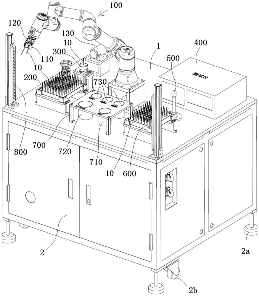
The invention discloses a calibration system, comprising: a resistance detector, suitable for detecting the resistance of an electronic device; a first container, containing an etching solution suitable for etching lead wires; and a heater, suitable for heating the electronic device. When the first resistance of the electronic device at the first temperature detected by the resistance detector is within the first predetermined range, use the heater to heat the electronic device to a second temperature higher than the first temperature, and use the resistance detector to detect The second resistance of the electronic device at the second temperature, if the detected second resistance is outside the second predetermined range, the lead wire is etched with an etching solution to adjust the resistance value of the electronic device until the electronic device is at the second The second resistance at temperature is within a second predetermined range such that the resistance of the electronic device meets predetermined accuracy requirements. The invention reduces the manufacturing difficulty of the electronic device, and can also reduce the reject rate and save the manufacturing cost.

Description

technical field [0001] The invention relates to a calibration system and a calibration method suitable for calibrating the resistance of electronic devices. Background technique [0002] In the prior art, the resistance of the electronic device should meet a predetermined accuracy requirement, that is, the resistance of the manufactured electronic device should be within a predetermined range. In order to ensure that the resistance of the manufactured electronic device can meet the predetermined accuracy requirements, the manufacturing accuracy must be improved, which increases the manufacturing difficulty. [0003] In the prior art, if the resistance of the manufactured electronic device is not within the predetermined range, the electronic device becomes a waste product and will be directly discarded, which will cause great waste. Contents of the invention [0004] The purpose of the present invention is to solve at least one aspect of the above-mentioned problems and d...

Claims


Application Information

Patent Timeline
Patent Type & Authority Patents(China)
IPC IPC(8): G01D18/00
CPCG01D18/00C23F1/08G01R31/013H01C17/2416H01C17/265C23F1/14
Inventor 谢逢春邓颖聪张丹丹胡绿海刘云鲁异吴海东肖辉
Owner TYCO ELECTRONICS (SHANGHAI) CO LTD
Learn More