In-orbit compensation method for deformation of spaceborne microwave remote sensing instrument

A technology of spaceborne microwave and compensation method, which is applied in the directions of instruments, radio wave measurement systems, satellite radio beacon positioning systems, etc., can solve problems such as the inability to fully describe the deformation mechanism of scanning microwave imaging instruments, and achieve a wide range of applications and universal use. The effect of strong performance and simple calculation method

Active Publication Date: 2019-07-05
SHANGHAI SATELLITE ENG INST
View PDF3 Cites 7 Cited by
  • Summary
  • Abstract
  • Description
  • Claims
  • Application Information

AI Technical Summary

Problems solved by technology

However, this method simplifies the modeling of the internal distortion of the instrument, an

Method used


Image

  • In-orbit compensation method for deformation of spaceborne microwave remote sensing instrument
  • In-orbit compensation method for deformation of spaceborne microwave remote sensing instrument
  • In-orbit compensation method for deformation of spaceborne microwave remote sensing instrument

Examples


Embodiment

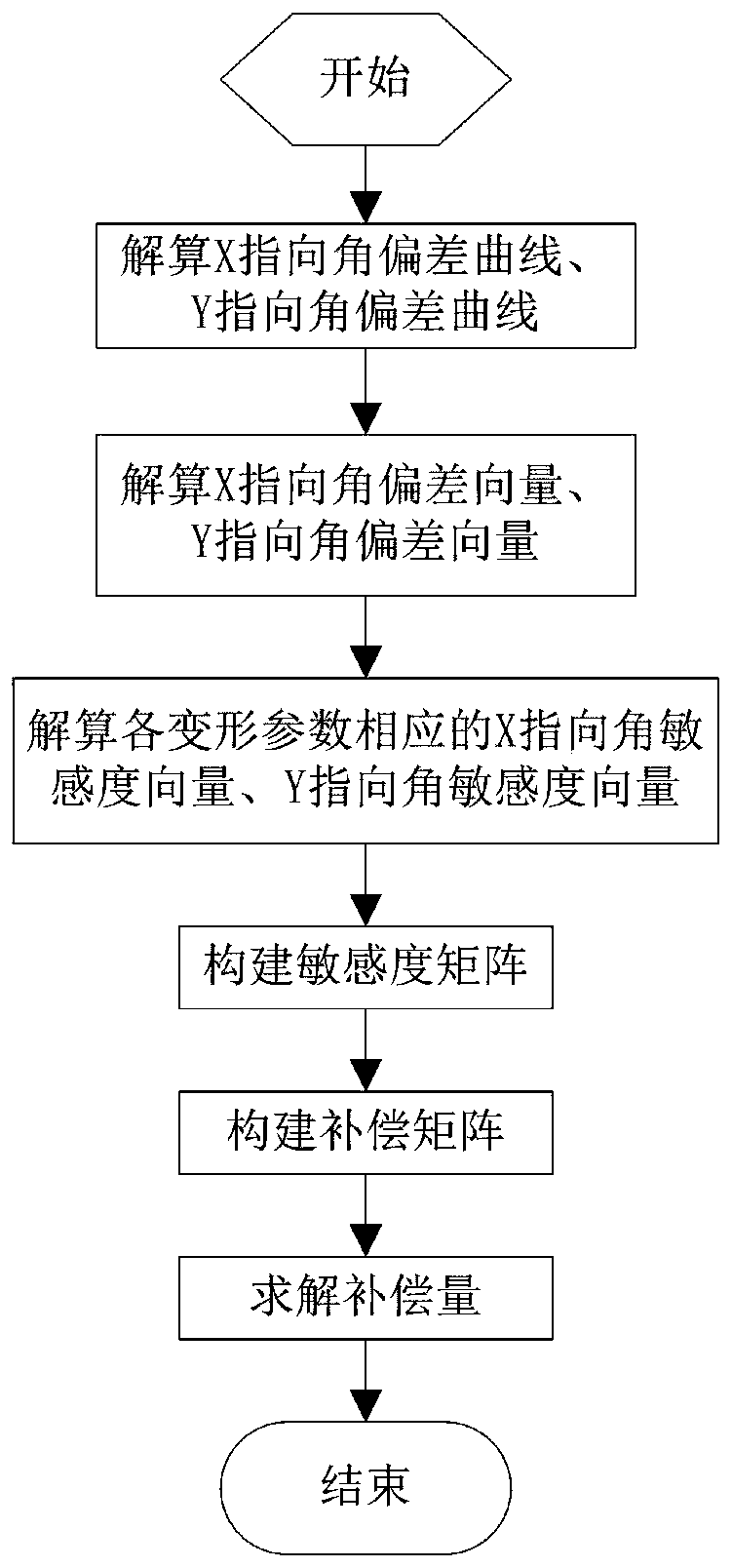
[0052] In this embodiment, the on-orbit compensation method for the deformation of the satellite-borne microwave remote sensing instrument of the present invention includes the following steps:

[0053] Step 1, the geometric calibration method solves the X pointing angle deviation curve and the Y pointing angle deviation curve of the view vector in the satellite body coordinate system;

[0054] Step 2, fitting the X pointing angle deviation curve and the Y pointing angle deviation curve through multi-order Fourier series, and solving the X pointing angle deviation vector and the Y pointing angle deviation vector;

[0055] Step 3, through the optical path model of the instrument, solve the corresponding X-pointing angle sensitivity curve and Y-pointing angle sensitivity curve of each deformation error parameter;

[0056] Step 4, fitting the X-directed angular sensitivity curve and the Y-directed angular sensitivity curve of each deformation parameter by multi-order Fourier seri...


PUM


Abstract

The invention relates to an in-orbit compensation method for the deformation of a spaceborne microwave remote sensing instrument. The method includes the following steps that: step 1, the X pointing angle deviation curve and Y pointing angle deviation curve of view vectors in a satellite body coordinate system are solved; and X pointing angle deviation vectors and Y pointing angle deviation vectors are solved; step 3, an X pointing angle sensitivity curve and a Y pointing angle sensitivity curve corresponding to various deformation error parameters are solved; step 4, X pointing angle sensitivity vectors and Y pointing angle sensitivity vectors corresponding to the deformation parameters are solved; step 5, a sensitivity matrix is constructed; step 6, a compensation matrix is constructed;and step 7, by means of the pseudo-inverse form of the compensation matrix, so that a compensation quantity is solved. An optical path model in the method of the invention is applicable to a spaceborne microwave remote sensing instrument comprising a planar reflecting surface, a rotating parabolic reflecting surface, a rotating hyperbolic reflecting surface and the like. With the method adopted, the in-orbit compensation quantities of the deformation of the optical path assemblies of spaceborne microwave remote sensing instruments of various configurations can be calculated.

Description

technical field [0001] The invention relates to the technical field of modeling methods for remote sensing instruments, in particular to an on-orbit compensation method for deformation of spaceborne microwave remote sensing instruments. Background technique [0002] Image positioning and registration is a key indicator that affects the quality of satellite remote sensing image products, and directly reflects the spatial correspondence between remote sensing image information and targets. It plays an important role in the quantitative application of remote sensing satellite business image product positioning, such as precise positioning of complex regional conditions, accurate tracking of severe weather, and generation of cloud image animations. [0003] Error sources such as satellite orbit and attitude drift, satellite thermal deformation, instrument servo error, attitude control system noise, and dynamic internal effects make the instrument line of sight deviate from the n...

Claims


Application Information

Patent Timeline
IPC IPC(8): G01S19/07G01B11/16
CPCG01B11/16G01S19/07
Inventor 刘华清吕旺董瑶海陈文强朱振华徐凯
Owner SHANGHAI SATELLITE ENG INST
Why Eureka
Try Eureka