
Crimping electrical connector

An electrical connector, crimping technology, applied in the direction of connecting, joining/disconnecting connecting parts, two-part connecting devices, etc., can solve the problems of insufficient electrical conductivity, slow conduction speed, and few contact points, etc. Achieve the effect of fast conduction speed, increase the passing current, and enhance the conductivity

Inactive Publication Date: 2019-07-05
REPOWER TECH CO LTD
View PDF7 Cites 0 Cited by
  • Summary
  • Abstract
  • Description
  • Claims
  • Application Information

AI Technical Summary

Problems solved by technology

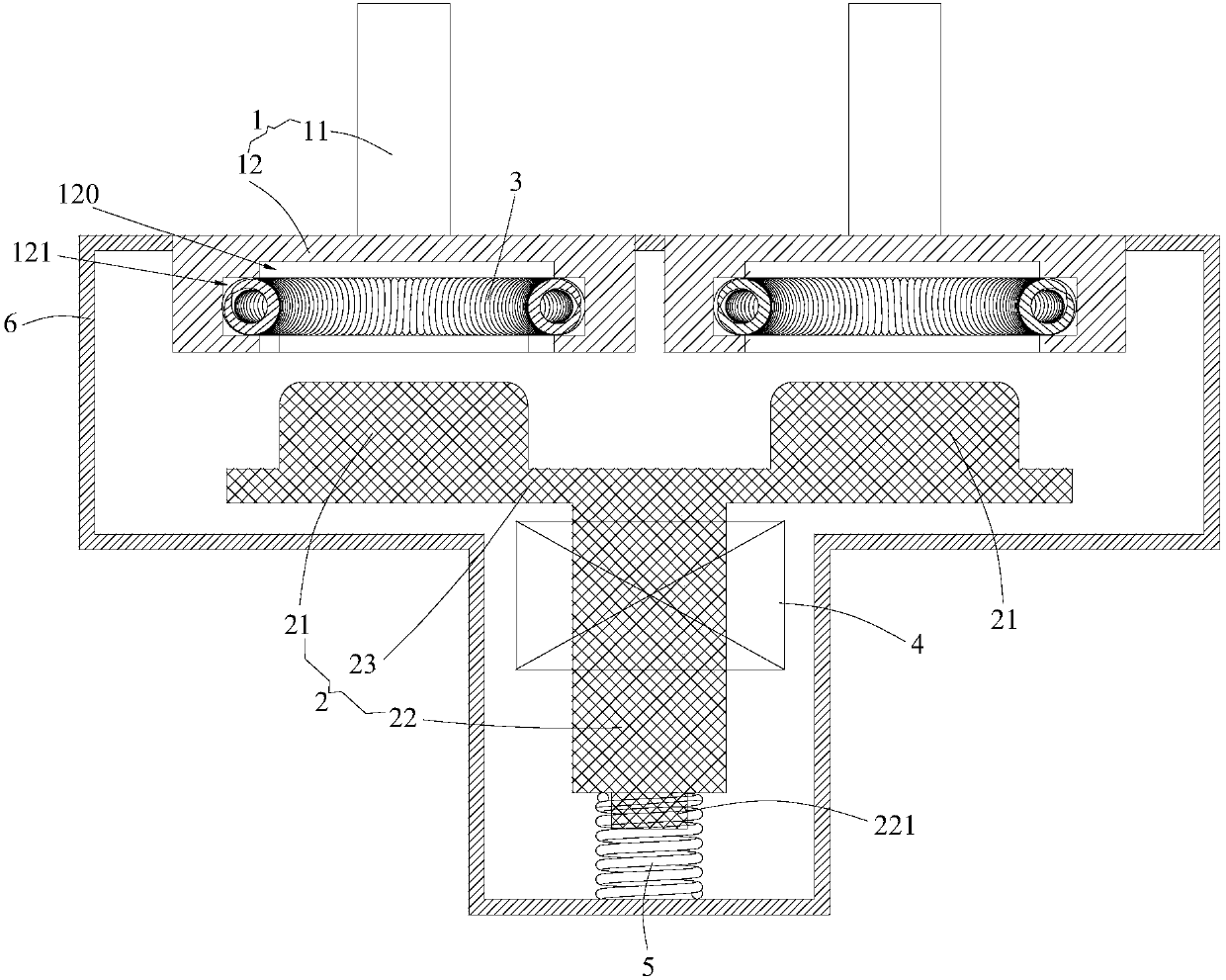
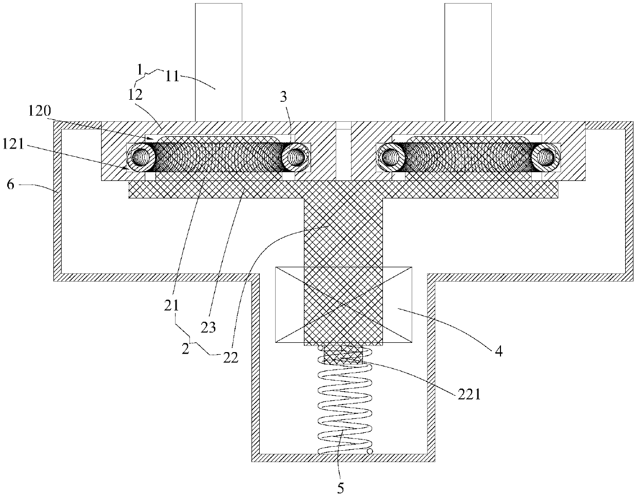
[0003] The purpose of the present invention is to provide a crimping type electrical connector to solve the problem of the narrow contact surface of two terminals and few contact points in the prior art, resulting in slow conduction speed and low conductivity. Insufficient technical issues

Method used


Image

  • Crimping electrical connector
  • Crimping electrical connector
  • Crimping electrical connector

Examples


Embodiment Construction

[0023] In order to make the technical problems, technical solutions and beneficial effects to be solved by the present invention clearer, the present invention will be further described in detail below in conjunction with the accompanying drawings and embodiments. It should be understood that the specific embodiments described here are only used to explain the present invention, not to limit the present invention.

[0024] It should be noted that when an element is referred to as being “fixed” or “disposed on” another element, it may be directly on the other element or be indirectly on the other element. When an element is referred to as being "connected to" another element, it can be directly connected to the other element or indirectly connected to the other element.

[0025] It is to be understood that the terms "length", "width", "top", "bottom", "front", "rear", "left", "right", "vertical", "horizontal", "top" , "bottom", "inner", "outer" and other indicated orientations...


PUM


Abstract

The present invention provides a crimping electrical connector. The crimping electrical connector comprises: wiring terminals provided with plug-in holes; a conduction piece comprising plug-in portions plugged into the plug-in holes and electrically connected with the wiring terminals; and conductive springs which perform encircling to form rings arranged in the plug-in holes, wherein the outer side walls of the conductive springs are butted against to the inner side walls of the plug-in holes, and the inner side walls of the conductive springs are butted against with the plug-in portions. Thecrimping electrical connector is provided with the plug-in hole, the plug-in portion and the conductive spring to allow the plug-in portion and the wiring terminal to be in full contact to reduce impedance, increase the pass-through current, improve the conduction speed and enhance the conductive capacity, and the conductive spring has a flexible capacity to allow the conduction piece to reduce the control intensity in the motion process.

Description

technical field [0001] The invention belongs to the technical field of power devices, and more specifically relates to a crimping type electrical connector. Background technique [0002] A crimp-type electrical connector is a device that connects two active devices for the transmission of electrical current and signals. The crimping type electrical connector generally includes two connection terminals, and is respectively electrically connected to an external circuit through the two conductive connection terminals to conduct the external circuit. In the prior art, due to the relatively narrow contact surface of the two terminals, and due to some manufacturing processes and other reasons, there are not many contact points between the two terminals, and the connection is not tight after contact. The crimping type electrical connector has slow conduction speed, insufficient conduction capacity, and very large conduction resistance. Contents of the invention [0003] The pur...

Claims


Application Information

Patent Timeline
IPC IPC(8): H01R13/02H01R13/04H01R13/187H01R13/62H01R13/631H01R13/635H01R24/00
CPCH01R13/02H01R13/04H01R13/187H01R13/6205H01R13/631H01R13/635H01R24/00
Inventor 毛广甫
Owner REPOWER TECH CO LTD
Learn More