Anti-loosening snap spring, anti-loosening structure, and in-position anti-loosening connector

A technology of anti-loosening and connectors, which is applied in the direction of connections, springs/shock absorbers, parts of connection devices, etc.

Pending Publication Date: 2019-07-05
CHINA AVIATION OPTICAL-ELECTRICAL TECH CO LTD
View PDF0 Cites 2 Cited by
  • Summary
  • Abstract
  • Description
  • Claims
  • Application Information

AI Technical Summary

Problems solved by technology

In some occasions, such as inside the nuclear island of a nuclear power plant or inside precision equipment, no excess is allowed, and the existence of screw nails becomes a hidden danger.

Method used


Image

  • Anti-loosening snap spring, anti-loosening structure, and in-position anti-loosening connector
  • Anti-loosening snap spring, anti-loosening structure, and in-position anti-loosening connector
  • Anti-loosening snap spring, anti-loosening structure, and in-position anti-loosening connector

Examples


Embodiment Construction

[0037] In order to further explain the technical means and effects of the present invention to achieve the intended purpose of the invention, the specific implementation, structure, characteristics and features of the in-place anti-loosening connector proposed according to the present invention will be described below in conjunction with the accompanying drawings and preferred embodiments. Its effect is described in detail below.

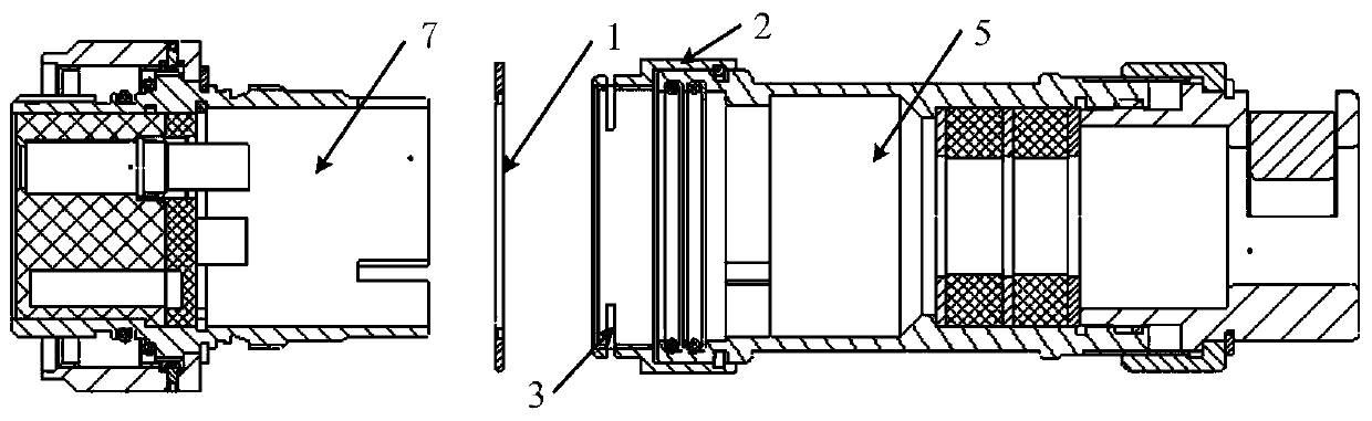
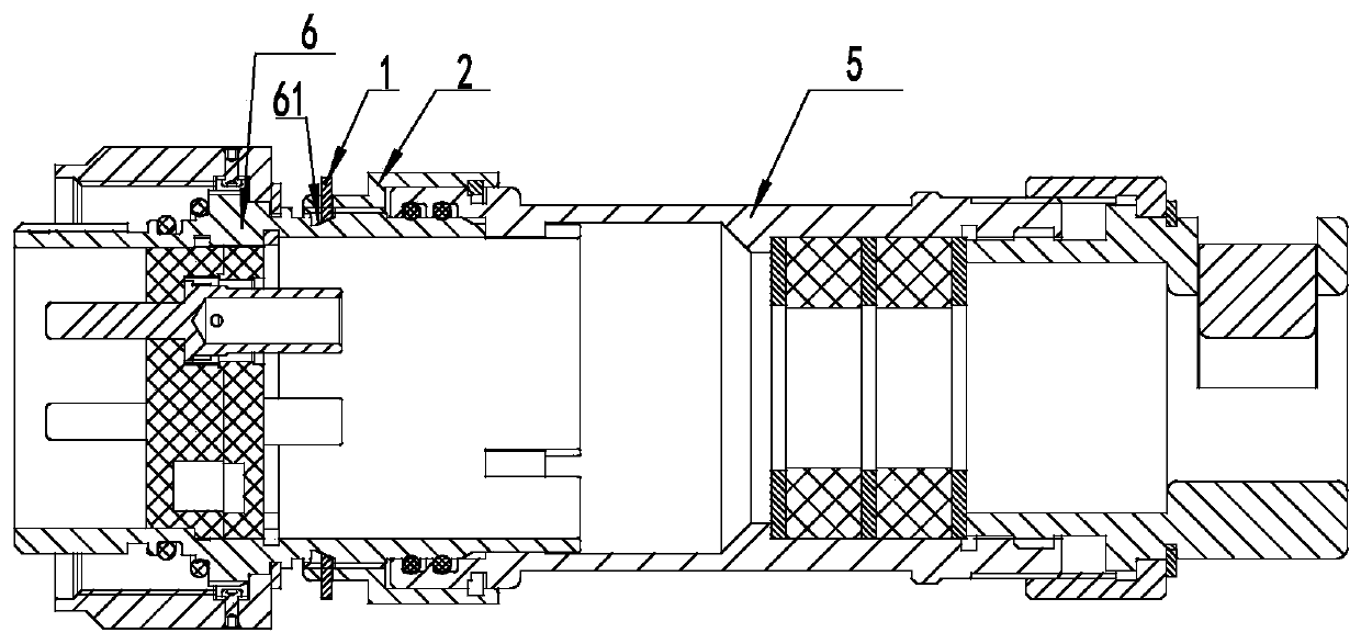
[0038] see Figure 1-5 , which is a structural schematic diagram of an anti-loosening connector in place according to an embodiment of the present invention. In the embodiment, the connector includes a first connecting part 5 and a second connecting part 7 whose front ends are butted, wherein the front end of the first connecting part 5 An anti-loosening structure for preventing the separation of the two connecting parts is fixed, and the anti-loosening structure includes a connecting nut 2 fixed on the first connecting part 5, and the connecting nu...


PUM


Abstract

The invention relates to an in-position anti-loosening connector including a first connecting member and a second connecting member that are connected to each other through the front ends thereof. Ananti-loosening structure for preventing the separation of the two connecting members is fixed to the front end of the first connecting member. The second connecting member housing is provided with ananti-loosening contact surface matching the anti-loosening structure. The anti-loosening structure comprises a connecting nut provided with an annular anti-loosening groove. The anti-loosening grooveis provided with a plurality of through engagement slots. The anti-loosening table of an anti-loosening snap spring passes through the through engagement slots. The anti-loosening surface of the anti-loosening table and the anti-loosening contact surface of the second connecting member housing are seamlessly attached to each other and maintain a certain tension. In addition, other parts except theanti-loosening table are trapped in the anti-loosening groove to achieve axial positioning.

Description

technical field [0001] The invention relates to the technical field of connectors, in particular to an anti-loosening connector in place. Background technique [0002] The function of the connector is to quickly connect and disconnect the signal or energy between the devices, which can divide the system into different unit blocks, which facilitates the modularization of the system and facilitates installation and maintenance. Connectors with cables often have accessories, which can clamp and seal the cables. The accessories are mainly fixed with screw nails. This fixing method is simple, easy to realize and convenient to install, but the screw screws still have the risk of loosening. In some occasions, such as inside the nuclear island of a nuclear power plant or inside precision equipment, no excess is allowed, and the existence of screw nails becomes a hidden danger. Contents of the invention [0003] In order to solve the above-mentioned problems, the present inventio...

Claims


Application Information

Patent Timeline
IPC IPC(8): H01R13/502H01R13/622F16F1/18
CPCF16F1/187H01R13/502H01R13/622
Inventor 时兴波薛欢欢牛志军江浪邵明坤顾玲童杜俊伟赵鹏坤
Owner CHINA AVIATION OPTICAL-ELECTRICAL TECH CO LTD
Why Eureka
Try Eureka