
Copper rotor super-efficient motor

An ultra-high-efficiency, copper rotor technology, applied to the magnetic circuit rotating parts, magnetic circuit shape/style/structure, etc., can solve the problems of large rotor resistance, motor heating, large rotor loss, etc., to achieve accurate positioning and prevent vibration , the effect of reducing noise

Inactive Publication Date: 2019-07-05
刘卫孟
View PDF0 Cites 0 Cited by
  • Summary
  • Abstract
  • Description
  • Claims
  • Application Information

AI Technical Summary

Problems solved by technology

[0003] During the operation of the motor, a large amount of heat will be generated due to the electromagnetic load and the friction between the parts, which will cause the motor to heat up, resulting in low motor efficiency. The existing motors generally use single-slot cast copper rotors. In view of the strength of the motor, the rotor core The use area of ​​the slot is limited, the rotor resistance is large, the rotor loss is large, and the motor efficiency is low; in addition, since the stacking degree of each rotor punching will affect the quality of the cast copper rotor, it is necessary to design a method that can ensure the rotor punching. The structure of the neat effect of stacking, thus further ensuring the efficiency of the motor

Method used


Image

  • Copper rotor super-efficient motor
  • Copper rotor super-efficient motor
  • Copper rotor super-efficient motor

Examples


Embodiment 1

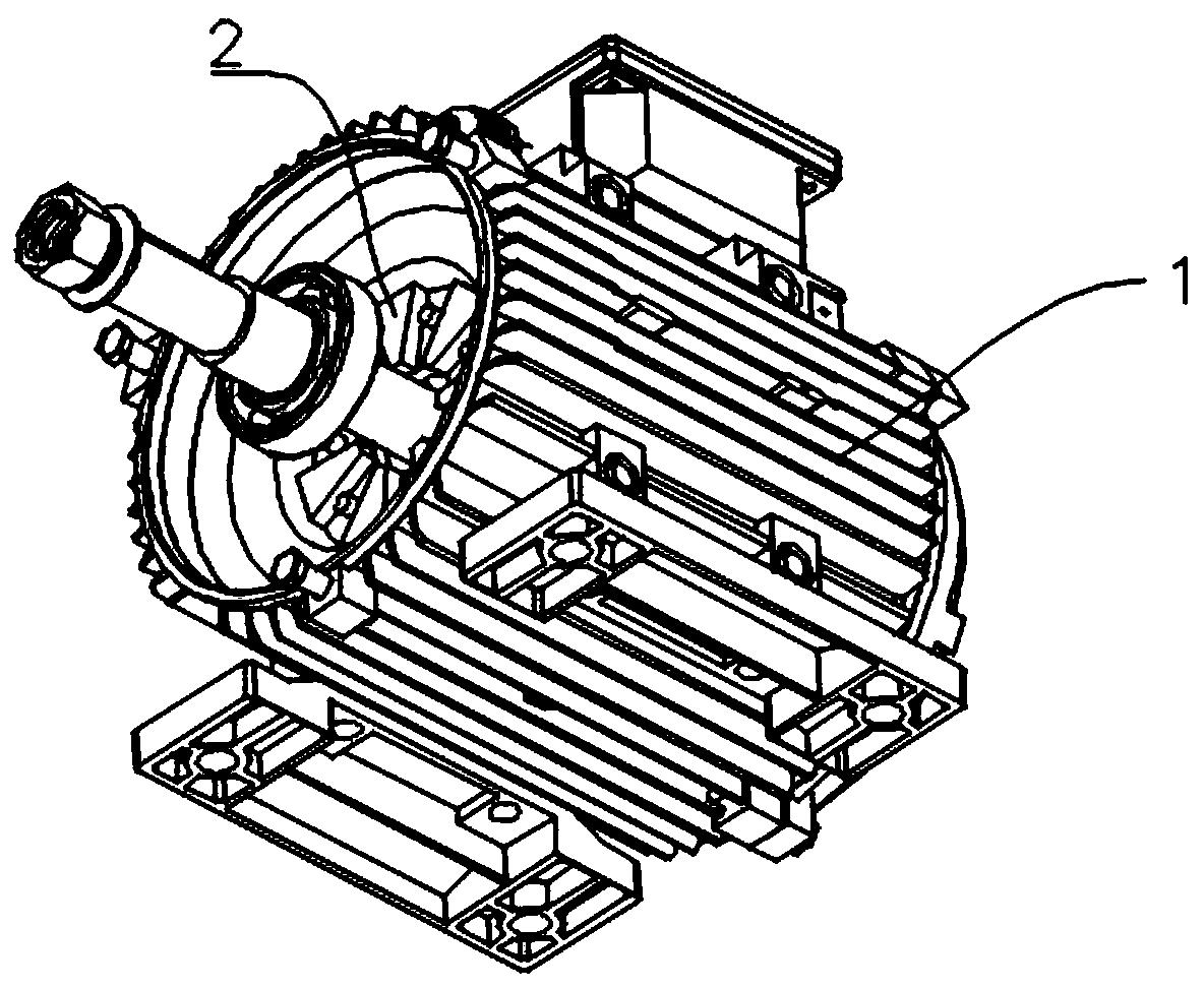
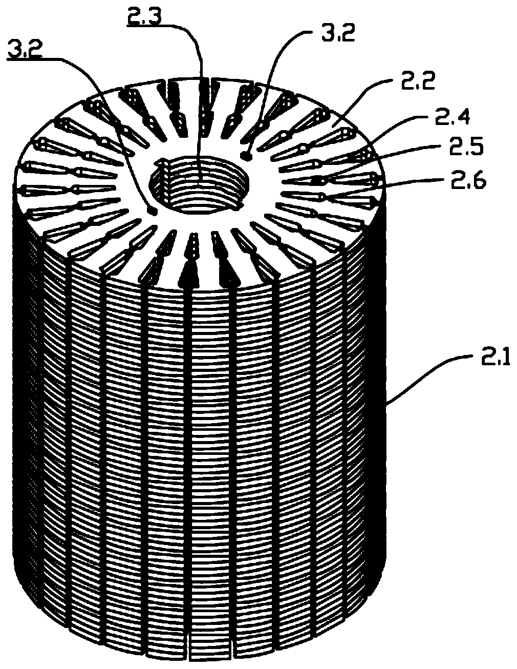
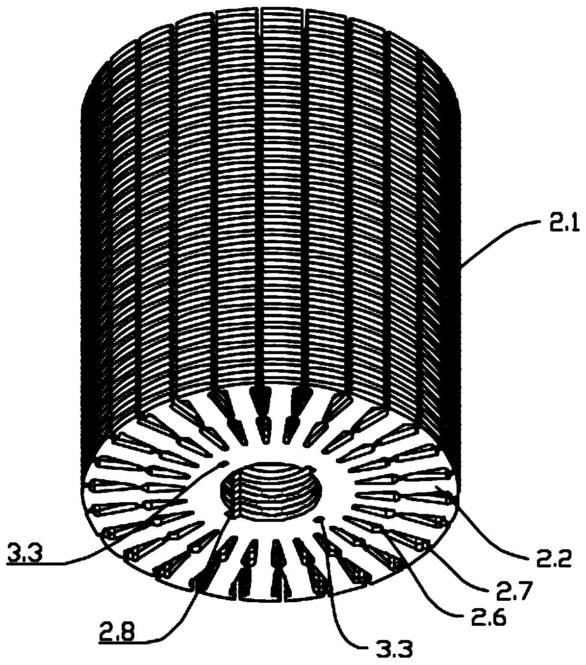
[0034] Such as Figure 1-Figure 6 As shown, this embodiment provides a copper rotor ultra-high-efficiency motor, including a housing 1, a stator installed in the housing 1, a rotor 2 installed in the stator, and a rotating shaft fixed at the center of the rotor 2. The rotor 2 includes a plurality of The rotor body 2.1 is formed by stacking the rotor punches 2.2. The rotor punches 2.2 are silicon steel sheets. The middle part of the rotor punches 2.2 is provided with a shaft connecting hole 2.3. The rotor punches 2.2 are evenly provided with two circles of die-casting around the rotation shaft connecting hole 2.3. Groove, the die-casting groove near the outer edge of the rotor punching plate 2.2 is the outer ring die-casting groove 2.4, the die-casting groove near the center of the rotor punching plate 2.2 is the inner ring die-casting groove 2.5, and the outer ring die-casting groove 2.4 and the inner ring die-casting groove 2.5 are provided Connecting details 2.6, the end of ...

Embodiment 2

[0038]This embodiment is optimized and defined on the basis of the above-mentioned embodiment 1.

[0039] In order to achieve the uniformity of rotor 2 casting copper pouring on the entire rotor 2 and ensure the efficiency of the motor, the number of outer ring die-casting grooves 2.4 and inner ring die-casting grooves 2.5 are consistent and correspond one-to-one. The outer ring die-casting grooves 2.4 and the inner ring die-casting groove 2.5. The axes of the connection detail 2.6 and the notch 2.7 are consistent.

Embodiment 3

[0041] This embodiment is optimized and defined on the basis of the above-mentioned embodiment 2.

[0042] The width of the end connecting the die-casting groove 2.4 of the outer ring to the notch 2.7 is greater than the width of the end connecting the die-casting groove 2.4 of the outer ring to the connecting detail 2.6; the width of the end connecting the die-casting groove 2.5 of the inner ring to the connecting detail 2.6 is greater than that The width of one end of the middle part of the rotor punching sheet 2.2.


PUM


Abstract

The invention relates to the technical field of motors, and discloses a copper rotor super-efficient motor. The copper rotor super-efficient motor comprises a shell, a stator installed inside the shell, a rotor installed inside the stator and a rotating shaft fixed at the center of the rotor; the rotor comprises a rotor body formed by stacking a plurality of rotor sheets; a rotating shaft connecting hole is arranged at the middle portion of the rotor sheets; and two circles of die casting grooves are uniformly arranged on the rotor sheets around the circumferential direction of the rotating shaft connecting hole, and the die casting groove close to the outer edges of the rotor sheets is an outer ring die casting groove. The copper rotor super-efficient motor provided by the invention is small in rotor loss and high in motor efficiency.

Description

technical field [0001] The invention relates to the technical field of motors, in particular to a copper rotor ultra-high-efficiency motor. Background technique [0002] The conductivity of pure aluminum is 60% IACS, and the conductivity of pure copper is 100% IACS. Copper has excellent wire performance and thermal conductivity, so that the cast copper rotor motor can achieve the advantages of improving efficiency and reducing temperature rise. Based on copper The high conductivity of the cast copper rotor motor can reduce the size, weight and cost of the motor through reasonable design and optimization of the motor structure. [0003] During the operation of the motor, a large amount of heat will be generated due to the electromagnetic load and the friction between the parts, which will cause the motor to heat up, resulting in low motor efficiency. The existing motors generally use single-slot cast copper rotors. In view of the strength of the motor, the rotor core The use...

Claims


Application Information

Patent Timeline
IPC IPC(8): H02K1/28H02K1/32H02K1/22
CPCH02K1/22H02K1/28H02K1/32
Inventor 刘卫孟任学明
Owner 刘卫孟
Learn More