
Oscillation circuit and oscillator

An oscillation circuit, amplifying circuit technology, applied in the direction of electric pulse generator circuit, differential amplifier generating pulse, active element generating pulse, etc., can solve problems such as poor reliability

Active Publication Date: 2019-07-05
XIANGTAN UNIV
View PDF4 Cites 0 Cited by
  • Summary
  • Abstract
  • Description
  • Claims
  • Application Information

AI Technical Summary

Problems solved by technology

[0004] Based on this, it is necessary to provide an oscillating circuit and an oscillator for the problem of poor output reliability of the traditional oscillating circuit

Method used


Image

  • Oscillation circuit and oscillator
  • Oscillation circuit and oscillator
  • Oscillation circuit and oscillator

Examples


Embodiment Construction

[0023] In order to facilitate understanding of the present application, the present application will be described more fully below with reference to the related drawings. The preferred embodiments of the present application are shown in the accompanying drawings. However, the application may be implemented in many different forms and is not limited to the embodiments described herein. Rather, these embodiments are provided so that a thorough and complete understanding of the disclosure of this application is provided.

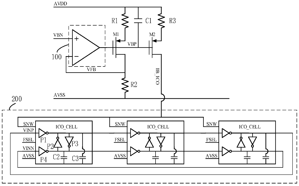
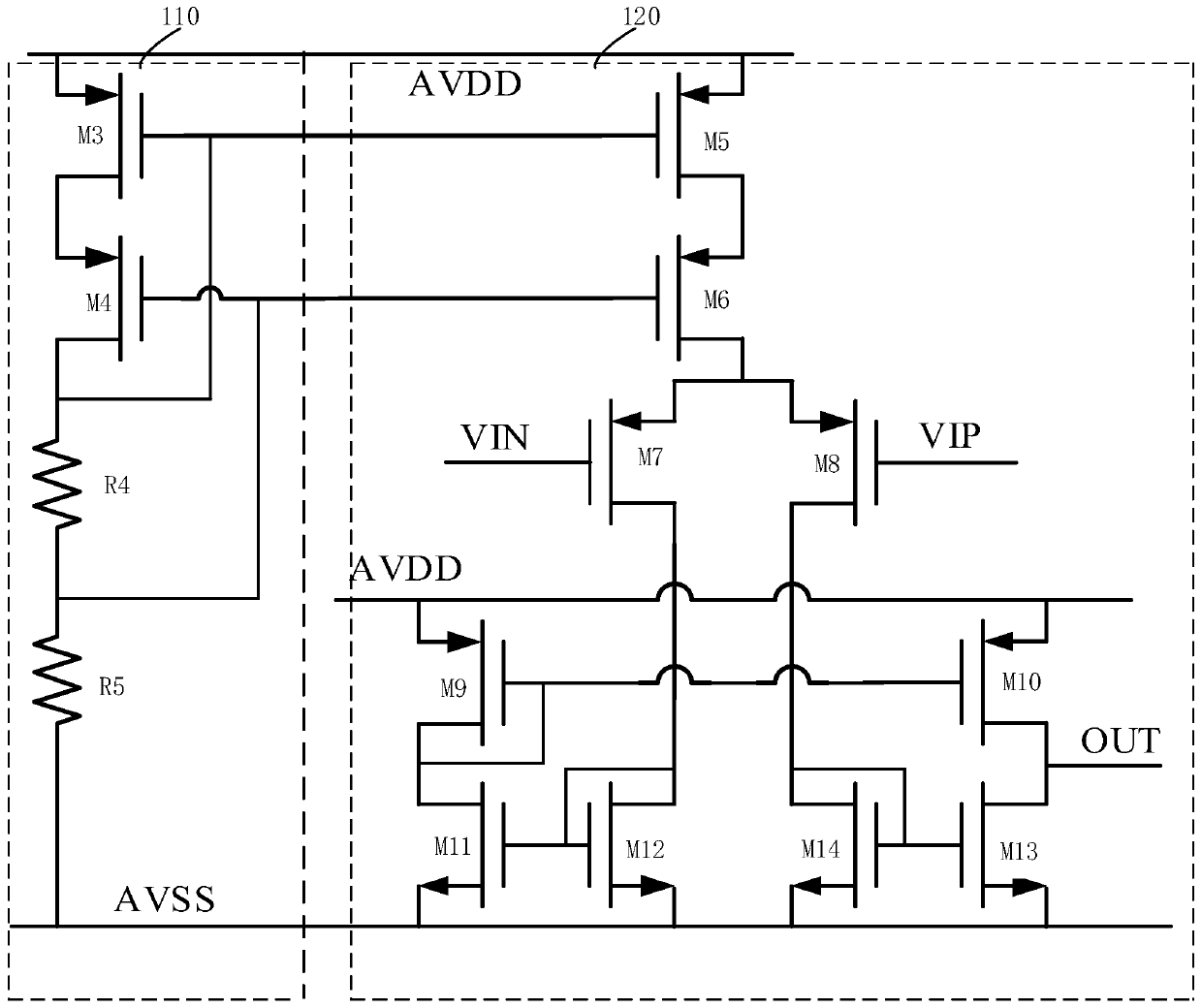
[0024] see figure 1 , an oscillating circuit, comprising: an operational amplifier circuit 100, a resistor R1, a resistor R2, a resistor R3, a switch tube M1, a switch tube M2, a capacitor C1 and a delay circuit 200, and the positive input end of the operational amplifier circuit 100 is used to connect an external Power supply, the output end of the operational amplifier circuit 100 is connected to the control end of the switch tube M1, the input end of the s...


PUM


Abstract

The invention relates to an oscillating circuit and an oscillator. A current-voltage negative feedback circuit composed of a resistor R1, a resistor R2, a resistor R3, a switch tube M1, a switch tubeM2 and a capacitor C1 is arranged at the reverse input end of an operational amplification circuit. the control voltage transmitted from the external power supply to the operational amplifier circuitis approximately equal to the output voltage of the operational amplifier circuit under the clamping action of the operational amplification circuit; the output voltage of the operational amplifier circuit interacts with the resistor R1 to form a leakage current in direct proportion to the control voltage, and according to a formula, the leakage current of the switch tube M1 is equal to that of the switch tube M2, and the leakage current is in direct proportion to the control voltage of the oscillating circuit. Based on the clamping effect of the operational amplification circuit and the current characteristic of the switch tube, the control voltage of the oscillation circuit is converted into the current in direct proportion to the control voltage, the oscillation frequency of the oscillation circuit is further controlled, and the linearity of the oscillation circuit is improved.

Description

technical field [0001] The present application relates to the field of circuit technology, and in particular, to an oscillator circuit and an oscillator. Background technique [0002] The oscillator circuit is a clock circuit that can generate a fixed frequency. The CMOS (Complementary Metal Oxide Semiconductor) ring oscillator circuit has the advantages of simple structure, easy integration and wide tuning range, and is widely used in various on-chip integrated systems. . With the continuous improvement of the CMOS technology level, the lower and lower supply voltage and the influence of the deep sub-micron effect bring greater challenges to the design of CMOS ring oscillator circuits. [0003] The linearity of the oscillation circuit and the adjustment range of the control voltage are contradictory. In the traditional oscillation circuit, if a higher control voltage adjustment range is to be obtained, the linearity of the oscillation circuit will be reduced, which is inco...

Claims


Application Information

Patent Timeline
IPC IPC(8): H03K3/021H03K3/023
CPCH03K3/021H03K3/023
Inventor 郭建刘克赛李林旭
Owner XIANGTAN UNIV
Learn More