Supercharge Your Innovation With Domain-Expert AI Agents!

Bearing for a crusher, and crusher

A crusher, gyratory crusher technology, applied in the direction of bearing components, shafts and bearings, mechanical equipment, etc., can solve problems such as expensive maintenance of crusher downtime, bearing damage, etc., to achieve the effect of increasing the effective load bearing surface area

Inactive Publication Date: 2019-07-05
THYSSENKRUPP IND SOLUTIONS AG +1
View PDF5 Cites 0 Cited by
  • Summary
  • Abstract
  • Description
  • Claims
  • Application Information

AI Technical Summary

Problems solved by technology

[0002] Damage to the bearings may occur in overload situations where constituent parts of the rock volume to be broken may break with relative difficulty or fail to break
The result is costly repairs and unwanted crusher downtime

Method used


Image

  • Bearing for a crusher, and crusher
  • Bearing for a crusher, and crusher
  • Bearing for a crusher, and crusher

Examples


Embodiment Construction

[0022] In the various figures, identical components are always provided with the same reference numerals and are therefore usually also named or mentioned only once in each case.

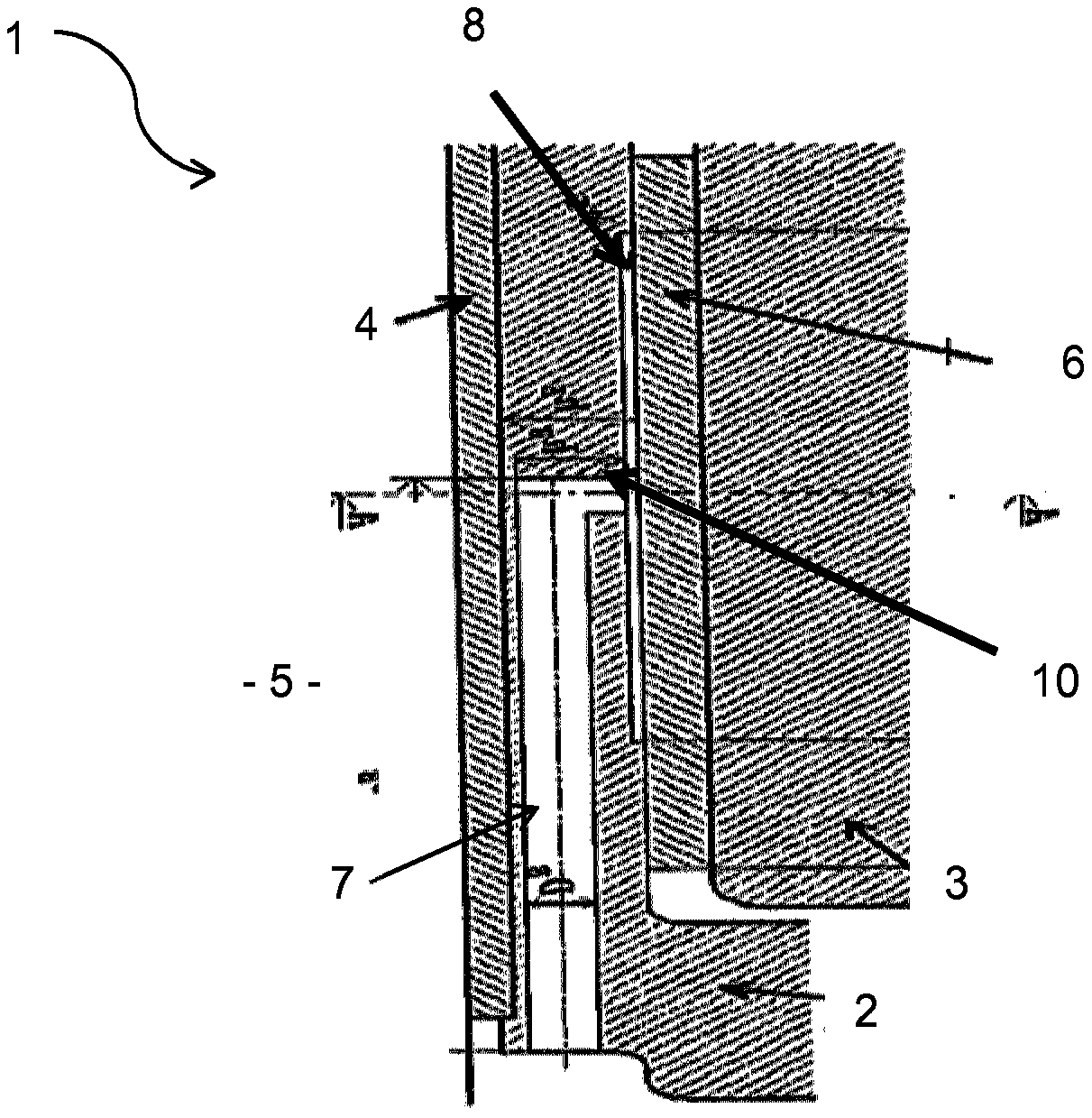
[0023] figure 1 A section extending parallel to the axial direction shows a bearing 1 for a crusher, in particular a slide bearing, according to an exemplary embodiment of the invention. A crusher is basically understood to mean a machine provided for crushing agglomerated material, especially rock, to form smaller particle sizes. Specifically, it is a cone crusher or a gyratory crusher. Here, comminution takes place in an annular gap that opens and closes in a cyclical manner between the crusher housing (not shown) and the crusher cone (not shown). Here, the opening and closing of the annular gap takes place simultaneously on opposite sides of the crushing space. In order to achieve the relative movement between the crusher housing and the crusher cone (this relative movement is the reason for t...


PUM


Abstract

The invention relates to a bearing for a crusher, in particular for a gyratory crusher or cone crusher, wherein the bearing has: a housing; an eccentric bush mounted in the housing for rotation aboutan axis; and a running bush arranged between the housing and the eccentric bush, wherein a lubricant line for supplying lubricant to the running bush is introduced into the eccentric bush.

Description

technical field [0001] The invention relates to a bearing for a crusher and the crusher, in particular to a cone crusher or a gyratory crusher. A crusher of this type is known for example from EP1711266B1 and is used for crushing rocks or minerals into smaller particle sizes. Here, the bearing is used to bring about a rolling movement of the crusher cone relative to the crusher housing, so that a constantly open and closed annular gap is formed between the crusher cone and the crusher housing, via which the Crack rocks. In order to achieve the tumbling motion, the bearing accordingly comprises an eccentric bush which rotates about the axis. Here, the eccentric bushing is at least partially surrounded by a bearing bushing or sleeve entering the housing. Background technique [0002] Damage to the bearings may occur in the event of an overload caused by constituents in the rock volume to be broken which may or may not be broken in a relatively difficult manner. The result ...

Claims


Application Information

Patent Timeline
Patent Type & Authority Applications(China)
IPC IPC(8): F16C33/10B02C2/04
CPCB02C2/04F16C33/1055
Inventor 蒂莫·比肖夫戴维·苏德曼托马斯·哈格曼马克西米利安·普莱尔斯
Owner THYSSENKRUPP IND SOLUTIONS AG
Features
  • R&D
  • Intellectual Property
  • Life Sciences
  • Materials
  • Tech Scout
  • Unparalleled Data Quality
  • Higher Quality Content
  • 60% Fewer Hallucinations
Learn More